


MARK 3 USER INSTRUCTIONS ENGLISH 71569102 08-06
Page 52 of 68 flowserve.com
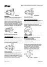
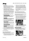
c) Install the outboard bearing.
Double row bearings
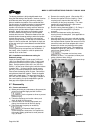
Install the outboard bearing [3013] firmly against
the shoulder as shown in figure 6-22. If hot
bearing mounting techniques are used, steps
must be taken to ensure the outboard bearing is
firmly positioned against the shaft shoulder. The
outboard bearing, while still hot, is to be
positioned against the shaft shoulder.
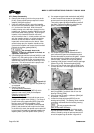
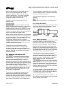
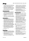
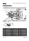
Duplex angular contact bearings
Duplex angular contact bearings must be
mounted back-to-back with the wider thrust sides
of the outer races in contact with each other as
shown in figure 6-25. Only bearings designed for
universal mounting should be used. The SKF
designation is “BECB”. NTN’s designation is “G”.
A special shaft is required when using
duplex angular contact bearings.)
Figure 25
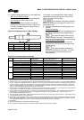
The orientation of the bearing
shields is different for horizontal pumps (figure 5-7)
and In-Line pumps (figure 5-8).
It must be understood that fixtures
and equipment used to press the bearing must be
designed so no load is ever transmitted through the
bearing balls. This would damage the bearing.
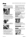
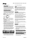
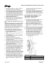
d) After the bearing has cooled below 38 °C (100 °F)
the bearing should be pressed against the shaft
shoulder. Figure 6-26 identifies the approximate
force needed to seat the bearing against the shaft
shoulder. If a press is not available the locknut
[3712] should be installed immediately after the
bearing is placed on the shaft and tightened to
ensure the bearing remains in contact with the shaft
shoulder. The locknut should then be retightened
repeatedly during the time the bearing is cooling.
Once cool the locknut should be removed.
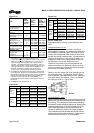
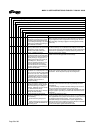
Figure 6-26
Pump Press force
N (lbf)
Locknut torque
Nm (lbf
Group 1 5 780 (1 300) 27 +4/-0 (20 +5/-0)
Group 2 11 100 (2 500) 54 +7/-0 (40 +5/-0)
Group 3 20 000 (4 500) 95 +7/-0 (70 +5/-0)
e) Install lockwasher [6541.1] and locknut [3712]. The
locknut should be torqued to the value shown in
figure 6-26. One tang on the lockwasher must be
bent into a corresponding groove on the locknut.
6.9.1.2 Bearing housing seals
Lip seals
If lip seals were used (see figure 6-16), install new lip
seals in the bearing carrier [3240] and the housing
[3200 - Group 1] or the adapter [1340 - Group 2 and 3].
The lip seals [4310.1 and 4310.2] are double lip style,
the cavity between these two lips should be
1
/
2
to
2
/
3
filled with grease. When installing this part, the large
metal face on the lip seal must face away from the
bearings.
Labyrinth seals
The following are general installation instructions
regarding the VBXX Inpro seal. Follow the instructions
provided with the seal by the manufacturer.
The elastomer O-ring located on the OD of the seal
has been sized to overfill the groove in which it is
located. When installing the seal into its
corresponding housing, in addition to compressing
the O-ring a certain amount of material may shear off.
This sheared material should be removed. An arbor
press should be used to install the seal.
Install the inboard seal in the bore of the bearing
housing (Group 1) or adapter (Group 2 and Group 3)
with the single expulsion port positioned at the 6
o’clock position.
Install the outboard seal in the bore of the bearing
carrier. There are no orientation issues since this is a
multiport design seal.
Magnetic seals
Follow the installation instructions provided by the
manufacturer.
6.9.1.3 Bearing carrier/power end assembly
a) Install new O-rings [4610.2] onto the bearing
carrier. Be sure to use the correct size O-rings.
(The Mark 3 and Mark 3A bearing carriers use
different O-rings.)
b) Slide the bearing carrier [3240] over the outboard
bearing [3013].
c) Install the outboard bearing retaining device.
Double row bearings on Group 1 and 2 pumps
Slide the snap ring [2530] in place with its flat
side against the outboard bearing and snap it into
its groove in the bearing carrier.
Duplex angular contact bearings on Group 1 and 2
pumps; all bearings on Group 3 pumps
Slide the bearing retainer [2530.1] against the
outboard bearing and install and tighten the
socket head capscrews [6570.12]. See figure 6-2
for correct torque values.