


MARK 3 USER INSTRUCTIONS ENGLISH 71569102 08-06
Page 20 of 68 flowserve.com
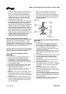
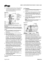
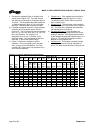
k) It should be noted that the connecting pipelines
must be individually supported, and that the
spring mounted baseplate is not intended to
support total static pipe loads.
Figure 4-4
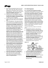
4.3.4.3 Stilt/spring mounted baseplates - motor
alignment
The procedure for motor alignment on stilt or spring
mounted baseplates is similar to grouted baseplates.
The difference is primarily in the way the baseplate is
leveled.
a) Level the baseplate by using the stilt adjusters.
(Shims are not needed as with grouted
baseplates.)
b) After the base is level, it is locked in place by
locking the stilt adjusters.
c) Next the initial pump alignment must be checked.
The vertical height adjustment provided by the
stilts allows the possibility of slightly twisting the
baseplate. If there has been no transit damage
or twisting of the baseplate during stilt height
adjustment, the pump and driver should be within
0.38 mm (0.015 in.) parallel, and 0.0025 mm/mm
(0.0025 in./in.) angular alignment. If this is not
the case, check to see if the driver mounting
fasteners are centered in the driver feet holes.
d) If the fasteners are not centered there was likely
shipping damage. Re-center the fasteners and
perform a preliminary alignment to the above
tolerances by shimming under the motor for
vertical alignment, and by moving the pump for
horizontal alignment.
e) If the fasteners are centered, then the baseplate
may be twisted. Slightly adjust (one turn of the
adjusting nut) the stilts at the driver end of the
baseplate and check for alignment to the above
tolerances. Repeat as necessary while
maintaining a level condition as measured from
the pump discharge flange.
f) Lock the stilt adjusters.
The remaining steps are as listed for new grouted
baseplates.
4.4 Grouting
a) The pump foundation should be located as close
to the source of the fluid to be pumped as
practical.
b) There should be adequate space for workers to
install, operate, and maintain the pump. The
foundation should be sufficient to absorb any
vibration and should provide a rigid support for
the pump and motor.
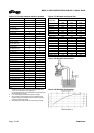
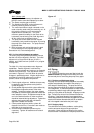
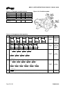
c) Recommended mass of a concrete foundation
should be three times that of the pump, motor
and base. Refer to figure 4-5.
Foundation bolts are imbedded in the
concrete inside a sleeve to allow some
movement of the bolt.
Figure 4-5
d) Level the pump baseplate assembly. If the
baseplate has machined coplanar mounting
surfaces, these machined surfaces are to be
referenced when leveling the baseplate. This may
require that the pump and motor be removed from
the baseplate in order to reference the machined
faces. If the baseplate is without machined
coplanar mounting surfaces, the pump and motor
are to be left on the baseplate. The proper
surfaces to reference when leveling the pump
baseplate assembly are the pump suction and
discharge flanges. DO NOT stress the baseplate.
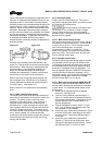
e) Do not bolt the suction or discharge flanges of
the pump to the piping until the baseplate
foundation is completely installed. If equipped,
use leveling jackscrews to level the baseplate. If
jackscrews are not provided, shims and wedges
should be used. (See Figure 4-5.) Check for
levelness in both the longitudinal and lateral
directions. Shims should be placed at all base
anchor bolt locations, and in the middle edge of
the base if the base is more than 1.5 m (5 ft.)
long. Do not rely on the bottom of the baseplate
to be flat. Standard baseplate bottoms are not
machined, and it is not likely that the field
mounting surface is flat.