


MARK 3 USER INSTRUCTIONS ENGLISH 71569102 08-06
Page 41 of 68 flowserve.com
Prior to resizing impellers in high
chrome iron and nickel, please consult your local
Flowserve sales representative.
6.2.1 Ordering of spare parts
Flowserve keeps records of all pumps that have been
supplied. Spare parts can be ordered from your local
Flowserve sales engineer or from a Flowserve
distributor or representative. When ordering spare
parts the following information should be supplied:
1) Pump serial number
2) Pump size and type
3) Part name – see section 8
4) Part item number – see section 8
5) Material of construction (alloy)
6) Number of parts required
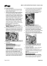
The pump size and serial number can be found on
the nameplate located on the bearing housing. (See
figure 3-1.)
6.3 Recommended spares and
consumable items
Mechanical process fluid seals, bearing housing lip
seals, bearings, shafting, impeller, and gaskets.
6.4 Tools required
A typical range of tools that will be required to
maintain these pumps is listed below.
Standard hand tools SAE
•
Hand wrenches
• Socket wrenches
• Allen wrenches
•
Soft mallet
• Screwdrivers
Specialized equipment
• Bearing pullers
• Bearing induction heaters
•
Dial indicators
• Spanner wrench
• Flowserve Mark 3 tool kit (see below)
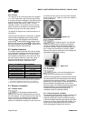
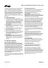
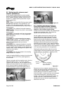
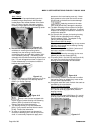
To simplify maintenance, it is recommended that the
Flowserve Mark 3 tool kit (shown in figure 6-1) is used.
This tool kit includes a handy impeller wrench, which
simplifies installation and removal of the impeller. It also
contains “nose cones” which protect shaft threads and
O-rings during maintenance. This tool kit can be
ordered from your local Flowserve sales engineer or
from a Flowserve distributor or representative.
Figure 6-1
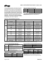
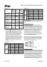
6.5 Fastener torques
Figure 6-2: Recommended bolt torques
Item Description
Group 1
non-lubricated
Group 2
non-lubricated
Group 3
non-lubricated
[6570.12]
Bearing retainer cap screws - standard bearings
n/a n/a
5
/
16
in. – 16 Nm (12 lbf•ft)
[6570.12]
Bearing retainer cap screws - duplex bearings
3
/
16
in. – 6 Nm (4 lbf•ft)
3
/
16
in. – 6 Nm (4 lbf•ft)
5
/
16
in. –16 Nm (12 lbf•ft)
[6570.5] Bearing housing/adapter cap screws and nuts n/a ½ in. – 54 Nm (40 lbf•ft) – 122 Nm (90 lbf•ft)
[6580.2] Mechanical seal gland studs/nuts, with gasket – 16 Nm (12 lbf•ft) – 16 Nm (12 lbf•ft) ½ in. – 41 Nm (30 lbf•ft)
[6580.2] Mechanical seal gland studs/nuts, with O-ring – 27 Nm (20 lbf•ft) – 27 Nm (20 lbf•ft) ½ in. – 54 Nm (40 lbf•ft)
[6580.1] Casing studs/nuts ½ in. – 41 Nm (30 lbf•ft)
½ in. – 41 Nm (30 lbf•ft)
– 81 Nm (60 lbf•ft)
¾ in. – 136 Nm (100 lbf•ft)
– 217 Nm (160 lbf•ft)
[6570.2] Cap screw cover/adapter (token bolts) – 27 Nm (20 lbf•ft) – 27 Nm (20 lbf•ft) ½ in. – 54 Nm (40 lbf•ft)
[6570.3] Bearing carrier set screws – 16 Nm (12 lbf•ft) ½ in. – 41 Nm (30 lbf•ft) ½ in. – 41 Nm (30 lbf•ft)
[6570.4] Cap screw foot ½ in. – 54 Nm (40 lbf•ft) ¾ in. – 217 Nm (160 lbf•ft)
1 in. – 300 Nm (228 lbf•ft)
[6570.13]
Cap screws - repeller cover to cover n/a – 16 Nm (12 lbf•ft) ½ in. – 41 Nm (30 lbf•ft)
[6570.15]
Cap screw – bearing housing ½ in. – 54 Nm (40 lbf•ft) ½ in. – 54 Nm (40 lbf•ft) n/a
[3712] Bearing Locknut
27 +4/-0 Nm (20 +5/-0 lbf•ft) 54 +7 / -0 Nm (40 +5 / -0 lbf•ft)
95 +7 / -0 Nm (70 +5 / -0 lbf•ft)
Notes:
1. For lubricated or PTFE-coated threads, use 75% of the values given.
2. Gasket joint torque values are for unfilled PTFE gaskets. Other gasket materials may require additional torque to seal.
Exceeding metal joint torque values is not recommended.