


MARK 3 USER INSTRUCTIONS ENGLISH 71569102 08-06
Page 30 of 68 flowserve.com
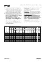
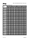
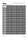
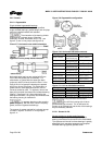
Figure 4-22: Allowable stand loads
F
T MAX
in N (lbf) F
N MAX
in N (lbf) Combination loading in N (lbf)
GP1 pumps
8 020
(1 800)
108 531
(24 400)
F
N
+ (13.556) F
T
F
N
+ (13.556) F
T
GP2 V-10 pumps
8 129
(1 827)
120 115
(27 004)
F
N
+ (0.0019) F
T
2
- (0.941) F
T
F
N
+ (0.0086) F
T
2
- (0.941) F
T
GP2 V-13 pumps
6 792
(1 535)
140 461
(31 579)
F
N
+ (0.0018) F
T
2
+ (8.453) F
T
F
N
+ (0.0079) F
T
2
+ (8.453) F
T
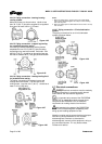
4.6.5 Pump and shaft alignment check
After connecting the piping, rotate the pump drive
shaft clockwise (viewed from motor end) by hand
several complete revolutions to be sure there is no
binding and that all parts are free. Recheck shaft
alignment (see section 4.5). If piping caused unit to
be out of alignment, correct piping to relieve strain on
the pump.
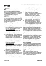
4.6.6 Auxiliary piping
4.6.6.1 Mechanical seal
When the pump is intended to be equipped with a
mechanical seal, it is Flowserve standard practice to
install the mechanical seal in the pump prior to
shipment. Specific order requirements may specify
that the seal be shipped separately, or none be
supplied. It is the pump installer’s responsibility to
determine if a seal was installed. If a seal was
supplied but not installed, the seal and installation
instructions will be shipped with the pump.
Failure to ensure that a seal is installed
may result in serious leakage of the pumped fluid.
Seal and seal support system must be installed and
operational as specified by the seal manufacturer.
The stuffing box/seal chamber/gland may have ports
that have been temporarily plugged at the factory to
keep out foreign matter. It is the installer’s
responsibility to determine if these plugs should be
removed and external piping connected. Refer to the
seal drawings and or the local Flowserve
representative for the proper connections.
4.6.6.2 Packing
When the pump is intended to be equipped with shaft
packing, it is not Flowserve standard practice to
install the packing in the stuffing box prior to
shipment. The packing is shipped with the pump. It
is the pump installer’s responsibility to install the
packing in the stuffing box.
Failure to ensure that the packing is
installed may result in serious leakage of the pumped
fluid.
4.6.6.3 Piping connection – seal/packing support
system
If the pump has a seal support system
it is mandatory that this system be fully installed and
operational before the pump is started.
If packing is used:
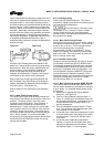
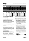
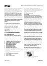
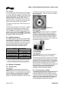
4.6.6.3a Packing lubrication
Water, when compatible with the pumpage, should be
introduced into tap V (figure 4-23) at pressure 69 to
103 kPa (10 to 15 lbf/in.
2
) above the stuffing box
pressure. The gland should be adjusted to give a flow
rate of 20 to 30 drops per minute for clean fluid. For
abrasive applications, the regulated flow rate should
be 0.06 to 0.13 l/s (1 to 2 US gpm).
Figure 4-23
Grease lubrication, when compatible with the liquid
being pumped, may be used. Again, introduced into
tap V.
In non-abrasive applications the liquid being pumped
may be sufficient to lubricate the packing without
need for external lines. Tap V should be plugged.
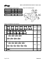
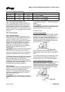
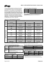
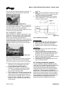
4.6.6.3b Abrasive packing arrangement
The installation procedures are the same as the standard
packing with some exceptions. A special lip seal is
installed first, followed by two seal cage assemblies, then
two of the packing rings provided (figure 4-24). A flush
line from a clean external source should be connected
via tap V, in the top of the stuffing box.
Figure 4-24