


MARK 3 USER INSTRUCTIONS ENGLISH 71569102 08-06
Page 42 of 68 flowserve.com
6.6 Setting impeller clearance and
impeller replacement
A new impeller gasket [4590.2] must be installed
whenever the impeller has been removed from the
shaft. Impeller clearance settings may be found in
section 5.3. Impeller balancing instruction may be
found in section 6.8.
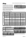
Mark 3 Unitized Self-Priming pumps require
that the outside diameter of the impeller be 3 mm
(0.125 in.) from the casing cutwater. If this close
clearance is not maintained the pump may not prime.
Do not adjust the impeller clearance
with the seal set. Doing so may result in seal leakage
and/or damage.
The impeller could have sharp edges,
which could cause an injury. It is very important to
wear heavy gloves.
It is recommended that two people
install a Group 3 impeller. The weight of a Group 3
impeller greatly increases the chance of thread
damage and subsequent lock-up concerns.
Do not attempt to tighten the impeller
on the shaft by hitting the impeller with a hammer or
any other object or by inserting a pry bar between the
impeller vanes. Serious damage to the impeller may
result from such actions.
Care should be taken in the handling
of high chrome iron impellers
Install the impeller [2200] by screwing it onto the shaft
(use heavy gloves) until it firmly seats against the
shaft shoulder.
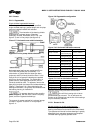
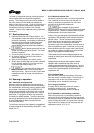
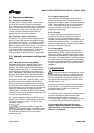
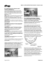
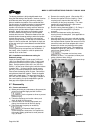
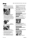
Tighten the impeller with the impeller wrench from the
Flowserve Mark 3 tool kit. To do this, grasp the
impeller in both hands and, with the impeller wrench
handle to the left (viewed from the impeller end of the
shaft - figure 6-3) spin the impeller forcefully in a
clockwise direction to impact the impeller wrench
handle on the work surface to the right (figure 6-4).
Figure 6-3
Figure 6-4
6.6.1 Installation and clearance setting for
reverse vane impellers on Mark 3 Standard,
Unitized self-priming, In-Line and open vane
impeller on the recessed impeller pump
Flowserve reverse vane impellers and recessed open
impellers are set off the cover. This allows the
impeller to be set without the casing.
Set the impeller clearance by loosening the set
screws [6570.3] and rotating the bearing carrier
[3240] to obtain the proper clearance. Turn the
bearing carrier counter-clockwise until the impeller
comes into light rubbing contact with the rear cover.
Rotating the shaft at the same time will accurately
determine this zero setting. Now, rotate the bearing
carrier clockwise to get the proper clearance. Refer
to figure 5-12 for the proper impeller clearance based
on the operating temperature for the application.
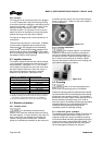
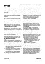
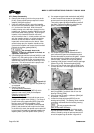
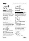
Rotating the bearing carrier the width of one of the
indicator patterns cast into the bearing carrier moves the
impeller axially 0.1 mm (0.004 in.). (See figure 6-5.)
Indicator
pattern
Rotation equivalent
to 0.1 mm (0.004 in)
axial movement
Figure 6-5
Determine how far to rotate the bearing carrier by
dividing the desired impeller clearance by 0.1 mm
(0.004 in) (one indicator pattern). Tightening the set
screws [6570.3] will cause the impeller to move
0.05 mm (0.002 in.) closer to the rear cover because
of the internal looseness in the bearing carrier
threads. This must be considered when setting the
impeller clearance. Rotate the bearing carrier
clockwise the required amount to get the desired
clearance to the cover.