


MARK 3 USER INSTRUCTIONS ENGLISH 71569102 08-06
Page 28 of 68 flowserve.com
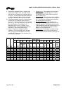
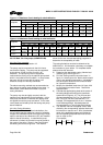
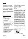
Figure 4-17: Maximum Y-axis loading for shaft deflection
Suction flange Discharge flange
Forces N (lbf) Moments Nm (lbf•ft) Forces N (lbf) Moments Nm (lbf•ft)
Pump size
Fxs Fys Fzs Mxs Mys Mzs Fxd Fyd Fzd Mxd Myd Mzd
Group 1 –
-8 896
(-2 000)
–
1 220.4
(900)
1 627.2
(1 200)
1 695
(1 250)
–
6 672
(1 500)
–
-678
(-500)
2 034
(1 500)
1 695
(1 250)
Group 2 –
-15 568
(-3 500)
–
1 762.8
(1 300)
1 762.8
(1 300)
4 068
(3 000)
–
11 120
(2 500)
–
-1 627
(-1 200)
2 034
(1 500)
4 068
(3 000)
Group 3 –
-22 240
(-5 000)
–
2 034
(1 500)
2 712
(2 000)
5 424
(4 000)
–
13 344
(3 000)
–
-1 695
(-1 250)
6 780
(5 000)
5 424
(4 000)
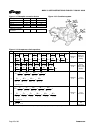
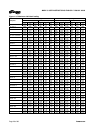
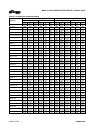
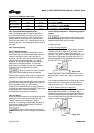
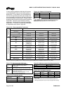
Figure 4-18: Maximum Z-axis loading for shaft deflection
Suction flange Discharge flange
Forces N (lbf) Moments Nm (lbf•ft) Forces N (lbf) Moments Nm (lbf•ft)
Pump size
Fxs Fys Fzs Mxs Mys Mzs Fxd Fyd Fzd Mxd Myd Mzd
Group 1
4 670
(1 050)
–
-5 560
(-1 250)
2 034
(1 500)
1 627
(1 200)
-3 390
(-2 500)
3 558
(800)
8 896
(2 000)
-13 344
(-3 000)
-2 034
(-1 500)
1 356
(1 000)
-3 390
(-2 500)
Group 2
15 568
(3 500)
–
-6 672
(-1 500)
2 034
(1 500)
1 763
(1 300)
-4 746
(-3 500)
6 227
(1 400)
11 120
(2 500)
-14 456
(-3 250)
-2 034
(-1 500)
2 915
(2 150)
-4 746
(-3 500)
Group 3
15 568
(3 500)
–
-8 896
(-2 000)
2 034
(1 500)
5 560
(4 100)
-5 424
(-4 000)
6 672
(1 500)
17 792
(4 000)
-15 568
(-3 500)
-2 034
(-1 500)
6 780
(5 000)
-5 424
(-4 000)
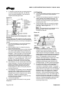
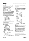
4.6.4.2 Mark 3 In-Line pumps (ASME B73.2M)
4.6.4.2a Pump mounting
Review Pump mounting, section 4.3.
The pump may be mounted such that it is free to
move with the piping. The pump may be supported
by the piping, so that it is free to move in all
directions. The pump may also be supported
underneath the casing or by the optional pump stand
which is not bolted to the foundation. In these cases,
the pump is free to move with the piping in all
directions except for vertically downward.
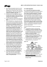
The above mounting methods are recommended as
they reduce the piping loads applied to the pump. In
these cases, nozzle loads are limited only by the
casing limitations.
The pump may also be rigidly mounted, with the
optional pump stand bolted to the foundation. In this
case pump movement is restricted and piping loads
are applied to both the pump and stand. In this case,
nozzle loads are limited by both the casing and pump
stand limitations.
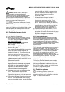
4.6.4.2b Casing limitations
To simplify or eliminate additional calculations, the
In-Line casing may be treated as a spool of schedule
40 pipe with a diameter equal to the discharge, length
equal to the face to face dimension (SD) and material
equal to that of the casing. In cases where pump
movement is limited, the constraint may be placed at
the center of the spool. Stress in the pump flanges
and bolting should not be ignored. This method
allows for the use of automated piping programs to
determine the acceptability of loads.
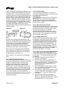
The casing limitations can also be determined by
ANSI/HI 9.6.2. All information necessary to complete
the evaluation is given below. For complete details
please review the standard.
a) Determine the appropriate casing “Nozzle load
material group” from figure 3-2.
b) Find the “Casing material correction factor” in
figure 4-11 based upon the “Nozzle load material
group” and operating temperature. Interpolation
may be used to determine the correction factor
for a specific temperature.
c) Multiply the allowable loads found in figure 4-20
by the material correction factor. Record the
adjusted loads.
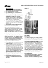
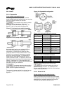
d) Calculate the applied piping loads at the center of
the casing flanges according to the coordinate
system found in figure 4-19. The 12 forces and
moments possible are Fxs, Fys, Fzs, Mxs, Mys,
Mzs, Fxd, Fyd, Fzd, Mxd, Myd and Mzd. For
example, Fxd designates force in the “x” direction
on the discharge flange. Mys designates the
moment about the “y”-axis on the suction flange.
e) The absolute value of the applied suction load
divided by the corresponding adjusted load must
be less than or equal to one. Also, the absolute
value of the applied discharge load divided by
the corresponding adjusted load must be less
than or equal to one.
For example:
,
0
.1.........................0.1,0.1
___
≤≤≤
adjz
zd
adjy
yd
adjx
xs
M
M
F
F
F
F