


MARK 3 USER INSTRUCTIONS ENGLISH 71569102 08-06
Page 11 of 68 flowserve.com
After unpacking, protection will be the responsibility of
the user. Addition of oil to the bearing housing will
remove the inhibitor. If units are to be idle for extended
periods after addition of lubricants, inhibitor oils and
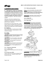
greases should be used. Every three months, the pump
shaft should be rotated approximately 10 revolutions.
2.5 Recycling and end of product life
At the end of the service life of the product or its parts,
the relevant materials and parts should be recycled or
disposed of using an environmentally acceptable
method and in accordance with local regulations. If the
product contains substances that are harmful to the
environment, these should be removed and disposed of
in accordance with current local regulations. This also
includes the liquids and/or gases that may be used in
the "seal system" or other utilities.
Make sure that hazardous substances are
disposed of safely and that the correct personal
protective equipment is used. The safety
specifications must be in accordance with the current
local regulations at all times.
3 DESCRIPTION
3.1 Configurations
The Durco Mark 3 chemical process pumps are
metallic , single stage, sealed, centrifugal pumps.
The horizontal family conforms to ASME B73.1M,
which has a centerline discharge and is represented
by our Standard, Sealmatic, Unitized self-priming,
Recessed impeller and Lo-Flo pump models. The
vertical pump or In-Line conforms to ASME B73.2M.
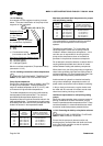
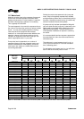
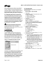
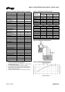
Figure 3-1: Nameplate mounted to housing
Serial No.
Equipment No.
Purchase Order
Model
Size
MDP
Material
Date DD/MMM/YY
2K6X4 M-13A/12.5 RV
The Prima
3 ™
is an ANSI 3A power end adapted to other
pump models from Flowserve as well as from other
pump manufacturers. Only the information in this
manual involving the ANSI 3A power end may be used
when Installing, Operating or Maintaining a pump that
has been upgraded to a Prima
3 ™
. All other information
regarding the pump type must be obtained from the
original pump manufacturer’s User Instructions.
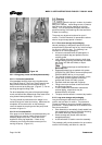
3.2 Nomenclature
The pump size will be engraved on the nameplate
typically as below:
2 K 6 X 4 M - 13 A /12.5 RV
• Frame size
“2" indicates a medium size pump frame (in this
example, a Group 2)
1 = Group 1 (small frame)
2 = Group 2 (medium frame)
3 = Group 3 (large frame)
•
Power end
K = Mark 3 style power end
Mark 3A – Standard
ANSI 3A – Optional (3 year guarantee)
J = Mark 3 style PE arranged for Mark 2 wet end
(No letter and no preceding number indicates a
Mark 2 power end)
• “6” = nominal suction port size (in.)
• “4” = Nominal discharge port size (in.)
• Modifier for “specialty pumps”
Blank or no letter = standard pump
M = Sealmatic
R = recessed impeller
US = unitized self-priming
V = vertical In-Line
LF = Lo-Flo
• Nominal maximum impeller diameter. “13” = 13 in.
• Pump design variation
A = This pump has been redesigned from an earlier
version. The impeller and casing are no longer
interchangeable with the earlier version.
H = This pump is designed for a higher flow capacity
than another pump with the same basic
designation. (Examples: 4X3-10 and 4X3-10H;
6X4-10 and 6X4-10H; 10X8-16 and 10X8-16H.
HH = This pump is designed for a higher head than
another pump with the same basic designation.
(Example: 4X3-13 and 4X3-13HH.)
• Actual impeller size
“12.5” = 12 ½ in. diameter; 8.13 = 8 LQ
10.75 = 10 ¾ in
(Previous annotation: 124 = 12
4
/
8
or 12 ½ in.
diameter; 83 = 8 LQ
• Impeller style
RV = reverse vane impeller; OP = Open impeller