


MARK 3 USER INSTRUCTIONS ENGLISH 71569102 08-06
Page 37 of 68 flowserve.com
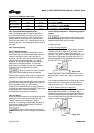
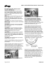
Only one side of the guard needs to be removed. To
reassemble simply reverse the above procedure.
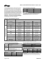
Figure 5-15
The coupling guard shown in figure 5-15 conforms to
the USA standard ASME B15.1, “Safety standard for
mechanical power transmission apparatus.”
Flowserve manufacturing facilities worldwide conform
to local coupling guard regulations.
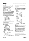
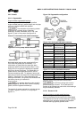
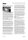
5.5.2 ClearGuard™ - optional
Flowserve offers as an option a ClearGuard™, which
allows you to see the condition of the coupling (see
figure 5-16). This guard can be used in place of the
existing clamshell guard described above.
Disassembly of the ClearGuard™ is accomplished by
removing the fasteners that hold the two guard halves
together followed by removing the foot bolts and
rotating the support leg out of the slot on the guard.
Figure 5-16
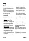
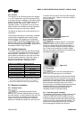
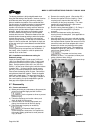
5.5.3 Trimming instructions
In order to correctly fit the pump/motor configuration,
each guard must be trimmed to a specific length.
This trimming is done on the motor end of the guard.
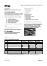
a) Measure minimum distance from the center of
mounting hole in the baseplate to the motor.
(If clam shell guard proceed to step c.)
b) Locate a reference center in the slot of the
ClearGuard™ coupling guard flange, see figure
5-17. Transfer the length measurement to the
guard using this reference center.
c) Trim the motor end of the guard according to the
above measurement. Trimming is best done with
a band saw, but most other types of manual or
power saws give acceptable results. Care must
be taken to ensure that there is no gap larger
than 6 mm (0.24 in.) between the motor and the
coupling guard.
d) If motor diameter is smaller than guard
diameter, trim guard so that it extends over the
end of the motor as far as possible.
e) Deburr the trimmed end with a file or a sharp
knife if ClearGuard™. Care must be taken to
eliminate all sharp edges.
Figure 5-17
5.5.4 Assembly instructions
Clam shell guard
a) Mount support leg to each clam shell, figure 5-15.
b) Attach one half of the guard to the baseplate.
c) Engage the tabs of guard halves together.
d) Attach the second support leg to the baseplate.
ClearGuard™
a) Place the bottom and top halves of the guard
around the coupling.
b) Install the support legs by inserting and then
rotating the tab on the leg through the slot in the
guard until it comes through and locks the top
and bottom halves of the guard together.
c) Attach the support legs to the baseplate using the
fasteners and washers provided.
d) Install fasteners in the holes provided to secure
the guard flanges together.
5.6 Priming and auxiliary supplies
The Mark 3 standard, Sealmatic, Recessed Impeller,
Lo-Flo, and In-Line centrifugal pump will not move liquid
unless the pump is primed. A pump is said to be
“primed” when the casing and the suction piping are
completely filled with liquid. Open discharge valves a
slight amount. This will allow any entrapped air to
escape and will normally allow the pump to prime, if the
suction source is above the pump. When a condition
exists where the suction pressure may drop below the
pump’s capability, it is advisable to add a low-pressure
control device to shut the pump down when the
pressure drops below a predetermined minimum.
Reference
center
Trim this end
Measurement step a)