


MARK 3 USER INSTRUCTIONS ENGLISH 71569102 08-06
Page 18 of 68 flowserve.com
4 INSTALLATION
Zirconium 702 or high chrome iron components
If any of the components of the pump
have been made of zirconium or high chrome iron,
the following precautionary measures should be
followed:
•
Use hand wrenches rather than impact wrenches
• This equipment should not be subjected to
sudden changes in temperature or pressure
•
Avoid striking this equipment with any sharp blows
Zirconium 705 and high chrome iron components
Avoid any repair or fabrication welds
on Zirconium 705 and high chrome iron components.
4.1 Location
The pump should be located to allow room for
access, ventilation, maintenance, and inspection with
ample headroom for lifting and should be as close as
practicable to the supply of liquid to be pumped.
Refer to the general arrangement drawing for the
pump set.
4.2 Part assemblies
The supply of motors and baseplates are optional.
As a result, it is the responsibility of the installer to
ensure that the motor is assembled to the pump and
aligned as detailed in section 4.5 and 4.8.
4.3 Foundation
4.3.1 Protection of openings and threads
When the pump is shipped, all threads and all
openings are covered. This protection/covering
should not be removed until installation. If, for any
reason, the pump is removed from service, this
protection should be reinstalled.
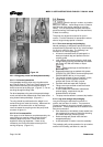
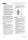
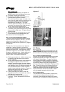
4.3.2 In-Line pump mounting
The Mark 3 In-Line can be supported in several ways:
• The pump may be supported by the piping; in
which case it is recommended that the suction
and discharge pipes be supported adjacent to the
pump nozzles
•
The pump may be supported under the casing
foot or on the optional “pump stand”
The “pump stand” will allow the pump to free stand
without the aid of piping. The pump stand may be
bolted (and grouted) into place. In this case, the
piping loads must be within the limits of the casing
and of the “pump stand” as found in section 4.6.
The most advantageous method is the one that
permits the pump to move with the piping. This
eliminates problems due to thermal expansion, as the
pump is designed to withstand forces that the piping
is normally capable of transmitting.
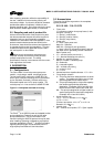
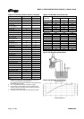
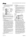
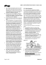
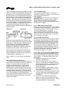
4.3.3 Rigid baseplates - overview
The function of a baseplate is to provide a rigid
foundation under a pump and its driver that maintains
alignment between the two. Baseplates may be
generally classified into two types:
• Foundation-mounted, grouted design. (Figure 4-1.)
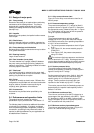
• Stilt mounted, or free standing. (Figure 4-2.)
Figure 4-1
Figure 4-2
Baseplates intended for grouted installation are
designed to use the grout as a stiffening member.
Stilt mounted baseplates, on the other hand, are
designed to provide their own rigidity. Therefore the
designs of the two baseplates are usually different.
Regardless of the type of baseplate used, it must
provide certain functions that ensure a reliable
installation. Three of these requirements are:
1. The baseplate must provide sufficient rigidity to
assure the assembly can be transported and
installed, given reasonable care in handling,
without damage. It must also be rigid enough
when properly installed to resist operating loads.
2. The baseplate must provide a reasonably flat
mounting surface for the pump and driver. Uneven
surfaces will result in a soft-foot condition that may
make alignment difficult or impossible. Experience
indicates that a baseplate with a top surface
flatness of 1.25 mm/m (0.015 in./ft) across the
diagonal corners of the baseplate provides such a
mounting surface. Therefore, this is the tolerance
to which we supply our standard baseplate.