


MARK 3 USER INSTRUCTIONS ENGLISH 71569102 08-06
Page 19 of 68 flowserve.com
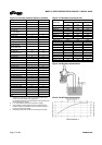
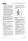
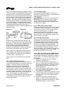
Some users may desire an even flatter surface,
which can facilitate installation and alignment.
Flowserve will supply flatter baseplates upon
request at extra cost. For example, mounting
surface flatness of 0.17 mm/m (0.002 in./ft) is
offered on the Flowserve Type E “Ten Point”
baseplate shown in figure 4-1.
3. The baseplate must be designed to allow the user
to final field align the pump and driver to within their
own particular standards and to compensate for
any pump or driver movement that occurred during
handling. Normal industry practice is to achieve
final alignment by moving the motor to match the
pump. Flowserve practice is to confirm in our shop
that the pump assembly can be accurately aligned.
Before shipment, the factory verifies that there is
enough horizontal movement capability at the motor
to obtain a “perfect” final alignment when the
installer puts the baseplate assembly into its
original, top leveled, unstressed condition.
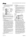
4.3.4 Stilt and spring mounted baseplates
Flowserve offers stilt and spring mounted baseplates.
(See figure 4-2 for stilt mounted option.) The low
vibration levels of Mark 3 pumps allow the use of
these baseplates - provided they are of a rigid design.
The baseplate is set on a flat surface with no tie down
bolts or other means of anchoring it to the floor.
General instructions for assembling these baseplates
are given below. For dimensional information, please
refer to the appropriate Flowserve “Sales print.”
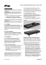
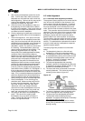
4.3.4.1 Stilt mounted baseplate assembly
instructions
Refer to figure 4-3.
a) Raise or block up baseplate/pump above the
floor to allow for the assembly of the stilts.
b) Predetermine or measure the approximate
desired height for the baseplate above the floor.
c) Set the bottom nuts [2] above the stilt bolt head
[1] to the desired height.
d) Assemble lock washer [3] down over the stilt bolt.
e) Assemble the stilt bolt up through hole in the
bottom plate and hold in place.
f) Assemble the lock washer [3] and nut [2] on the
stilt bolt. Tighten the nut down on the lock
washer.
g) After all four stilts have been assembled, position
the baseplate in place, over the floor cups [4]
under each stilt location, and lower the baseplate
to the floor.
h) Level and make final height adjustments to the
suction and discharge pipe by first loosening the
top nuts and turning the bottom nuts to raise or
lower the baseplate.
i) Tighten the top and bottom nuts at the lock
washer [3] first then tighten the other nuts.
j) It should be noted that the connecting pipelines
must be individually supported, and that the stilt
mounted baseplate is not intended to support
total static pipe load.
Figure 4-3
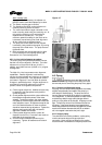
4.3.4.2 Stilt/spring mounted baseplate assembly
instructions
Refer to figure 4-4.
a) Raise or block up baseplate/pump above the
floor to allow for the assembly of the stilts.
b) Set the bottom nuts [4] above the stilt bolt head
[1]. This allows for 51 mm (2 in.) upward
movement for the final height adjustment of the
suction/discharge flange.
c) Assemble the lock washer [6] flat washer [5] and
bottom spring/cup assembly [2] down over the
stilt bolt [1].
d) Assemble the stilt bolt/bottom spring up through
hole in the bottom plate and hold in place.
e) Assemble top spring/cup assembly [3] down
over stilt bolt.
f) Assemble flat washer [5], lock washer [6] and
nuts [4] on the stilt bolt.
g) Tighten down top nuts, compressing the top
spring approximately 13 mm (0.5 in.). Additional
compression may be required to stabilize the
baseplate.
h) After all four stilts have been assembled,
position the baseplate in place, over the floor
cups [7] under each stilt location, and lower the
baseplate down to the floor.
i) Level and make final height adjustments to the
suction and discharge pipe by first loosening the
top nuts, and turning the bottom nuts to raise or
lower the baseplate.
j) Recompress the top spring to the compression
established in step g) and lock the nuts.