


MARK 3 USER INSTRUCTIONS ENGLISH 71569102 08-06
Page 29 of 68 flowserve.com
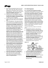
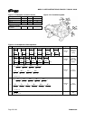
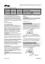
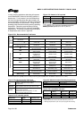
Figure 4-19
4.6.4.2c Pump stand limitations
In cases where the pump is rigidly mounted by the
pump stand, both the casing limitations and the pump
stand limitations must be satisfied. Due to the limited
load capacity of the pump stands, it may be
necessary to restrain the piping to prevent loads.
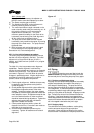
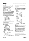
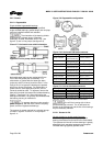
a) Ensure all applied loads are within the allowable
limits of the casing.
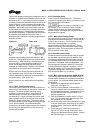
b) Translate the flange loads using the formulae
found in figure 4-21. Dimensional variables S
RS
,
S
RD
and R
S
can be found in figure 4-20.
c) Calculate F
T
and F
N
using the formulae found in
figure 4-21.
d) F
T
and F
N
must be less than F
TMAX
and F
NMAX
found in figure 4-22.
e) F
T
and F
N
must meet the combination formulae
found in figure 4-22.
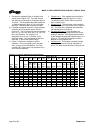
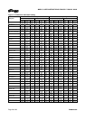
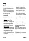
Figure 4-20: Dimensional data and casing limitations
Allowable casing loads (suction or discharge)
Dimensions
m (ft)
Forces N (lbf) Moments Nm (lbf•ft)
SD SRd SRs Rs Fx Fy Fz Mx My Mz
2x1.5V-6
0.381
(1.25)
0.191
(0.625)
0.191
(0.625)
0.163
(0.53)
1 824
(410)
17 685
(3 976)
1 824
(410)
692
(510)
976
(720)
692
(510)
2x1.5V-8
0.432
(1.42)
0.229
(0.75)
0.203
(0.67)
0.163
(0.53)
1 601
(360)
17 685
(3 976)
1 601
(360)
692
(510)
976
(720)
692
(510)
3x2V-7
0.432
(1.42)
0.203
(0.67)
0.229
(0.75)
0.163
(0.53)
2 824
(635)
28 147
(6 328)
2 824
(635)
1 120
(900)
1 722
(1 270)
1 120
(900)
3x1.5V-8
0.483
(1.58)
0.226
(0.74)
0.254
(0.83)
0.163
(0.53)
1 601
(360)
17 685
(3 976)
1 601
(360)
692
(510)
976
(720)
692
(510)
2x1.5V-10A
0.483
(1.58)
0.229
(0.75)
0.254
(0.83)
0.197
(0.65)
1 423
(320)
17 685
(3 976)
1 423
(320)
692
(510)
976
(720)
692
(510)
3x2V-10
0.508
(1.67)
0.241
(0.79)
0.267
(0.88)
0.197
(0.65)
2 402
(540)
28 147
(6 328)
2 402
(540)
1 120
(900)
1 722
(1 270)
1 120
(900)
4x3V-10
0.635
(2.08)
0.292
(0.96)
0.343
(1.13)
0.197
(0.65)
2 823
(638)
28 147
(6 328)
2 823
(638)
1 803
(1 330)
2 549
(1 880)
1 803
(1 330)
3x1.5V-13
0.61
(2.00)
0.292
(0.96)
0.318
(1.04)
0.248
(0.81)
1 134
(255)
17 685
(3 976)
1 134
(255)
692
(510)
976
(720)
692
(510)
3x2V-13
0.61
(2.00)
0.292
(0.96)
0.318
(1.04)
0.248
(0.81)
2 002
(450)
28 147
(6 328)
2 002
(450)
1 120
(900)
1 722
(1 270)
1 120
(900)
4x3V-13
0.711
(2.33)
0.33
(1.08)
0.381
(1.25)
0.248
(0.81)
2 535
(570)
28 147
(6 328)
2 535
(570)
1 803
(1 330)
2 549
(1 880)
1 803
(1 330)
6x4V-13
0.762
(2.50)
0.356
(1.17)
0.406
(1.33)
0.248
(0.81)
2 891
(650)
83 195
(18 704)
2 891
(650)
2 210
(1 630)
3 119
(2 300)
2 210
(1 630)
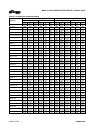
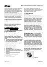
Figure 4-21: Pump stand load translation formulae
Forces Moments
F
XC
= F
XS
+ F
XD
M
XC
= M
XS
+ M
XD
+ (F
ZS
× SR
S
) - (F
ZD
× SR
D
)
F
YC
= F
YS
+ F
YD
M
YC
= M
YS
+ M
YD
F
ZC
= F
ZS
+ F
ZD
M
ZC
= M
ZS
+ M
ZD
- (F
XS
× SR
S
) + (F
XD
× SR
D
)
TMax
s
zc
yc
s
zc
xcT
F
R
M
F
R
M
FF ≤
×++
×+=
22
707.0707.0
MAXN
s
ycxc
zcN
F
R
MM
FF
_
707.0
≤
+
+=