


MARK 3 USER INSTRUCTIONS ENGLISH 71569102 08-06
Page 32 of 68 flowserve.com
The motor must be wired up in
accordance with the motor manufacturer’s
instructions (normally supplied within the terminal
box) including any temperature, earth leakage,
current and other protective devices as appropriate.
The identification nameplate should be checked to
ensure the power supply is appropriate.
See section 5.4, Direction of rotation,
before connecting the motor to the electrical supply.
For close coupled pumps it is necessary to wire the
motor with flexible conduit of sufficient length to allow
the motor/power end assembly to be moved back
from the casing for maintenance.
4.8 Final shaft alignment check
4.8.1 Horizontal pumps
a) Level baseplate if appropriate.
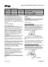
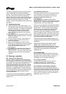
b) Mount and level pump if appropriate. Level the
pump by putting a level on the discharge flange.
If not level, adjust the footpiece as follows:
Mark 3A and ANSI 3 design
Add or delete shims [3126.1] between the
footpiece and the bearing housing.
Mark 3 design
Use the adjuster nut [6576] to adjust the
footpiece up or down.
c) Check initial alignment. If pump and driver have
been remounted or the specifications given below
are not met, perform an initial alignment as
described in section 4.5. This ensures there will
be sufficient clearance between the motor hold
down bolts and motor foot holes to move the
motor into final alignment. The pump and driver
should be within 0.38 mm (0.015 in.) FIM (full
indicator movement) parallel, and 0.0025 mm/mm
(0.0025 in./in.) FIM angular.
Stilt mounted baseplates
If initial alignment cannot be achieved with the motor
fasteners centered, the baseplate may be twisted.
Slightly adjust (one turn of the adjusting nut) the stilts
at the driver end of the baseplate and check for
alignment to the above tolerances. Repeat as
necessary while maintaining a level condition as
measured from the pump discharge flange.
d) Run piping to the suction and discharge to the
pump. There should be no piping loads
transmitted to the pump after connection is made.
Recheck the alignment to verify that there are no
significant changes.
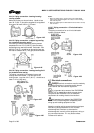
e) Perform final alignment. Check for soft-foot under
the driver. An indicator placed on the coupling,
reading in the vertical direction, should not indicate
more than 0.05 mm (0.002 in.) movement when
any driver fastener is loosened. Align the driver
first in the vertical direction by shimming
underneath its feet.
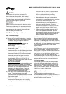
f) When satisfactory alignment is obtained the
number of shims in the pack should be
minimized. It is recommended that no more than
five shims be used under any foot. Final
horizontal alignment is made by moving the
driver. Maximum pump reliability is obtained by
having near perfect alignment. Flowserve
recommends no more than 0.05 mm (0.002 in.)
parallel, and 0.0005 mm/mm (0.0005 in./in.)
angular misalignment. (See section 6.8.4.7.)
g) Operate the pump for at least an hour or until it
reaches final operating temperature. Shut the
pump down and recheck alignment while the pump
is hot. Piping thermal expansion may change the
alignment. Realign pump as necessary.
4.8.2 Close coupled pumps
Alignment between the pump shaft and motor shaft is
built in by precise machining of the parts that position
these shafts. Parallel alignment of 0.018 mm (0.007 in.)
and angular alignment of 0.002 mm/mm (0.002 in/in)
can be expected. If a more refined alignment is desired,
it can be accomplished with the “C-Plus” optional
alignment feature.
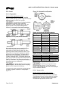
The C-Plus option requires that a spacer as shown in
section 8.9 be installed. Four adjusting screws are
used to push on the motor mounting studs to achieve
parallel alignment. The motor mounting fasteners
must be snug, but not tight during alignment. It may
be necessary to check the motor alignment with
motor fasteners tight. Corrections may be made until
the desired alignment is achieved. The motor
fasteners, adjusters and jam nuts should be tight.
4.8.3 In-Line pumps
The final field alignment follows the same procedure
as the initial alignment as described in section 4.5.2.
Maximum pump reliability is obtained by having near
perfect alignment. Flowserve recommends no more
than 0.05 mm (0.002 in.) parallel, and 0.0005 mm/mm
(0.0005 in./in.) angular misalignment.
4.9 Protection systems
The following protection systems are
recommended particularly if the pump is installed in a
potentially explosive area or is handling a hazardous
liquid. If in doubt consult Flowserve.