


Chapter 5 Installing the Tracer MP581 programmable controller
80 BAS-APG001-EN
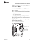
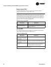
Binary output LEDs
The BO1–BO6 LEDs indicate the status of the six binary outputs.
Table 18 describes binary output LED activity.
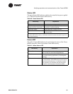
Service LED
The red Service LED indicates whether the controller is operating nor-
mally. Table 19 describes Service LED activity.
Note:
Each binary output LED reflects the status of the output relay on the
circuit board. It may or may not reflect the status of the equipment
the binary output is controlling. Field wiring determines whether the
state of the binary output LED also applies to the status of the end
device.
Table 18 describes the LED states.
Ta b le 1 8 . Binary output LEDs
LED activity Explanation
LED is on continuously The relay output is energized.
LED is off continuously The relay output is de-energized or there is no
power to the board.
Ta b le 1 9 . Red Service LED
LED activity Explanation
LED is off continuously
when power is applied to
the controller
The controller is operating normally.
LED is on continuously
when power is applied to
the controller
The controller is not working properly, or
someone is pressing the Service Pin button.
LED flashes once every
second
The controller is not executing the application
software because the network connections
and addressing have been removed.
1
1
Restore the controller to normal operation using the Rover service tool. Refer to
EMTX-SVX01D-EN for more information.