


Chapter 5 Installing the Tracer MP581 programmable controller
64 BAS-APG001-EN
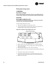
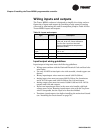
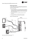
Wiring inputs and outputs
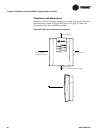
The Tracer MP581 enclosure is designed to simplify the wiring and con-
figuration of inputs and outputs by providing a large space for routing
wires and by eliminating the need to manipulate jumpers.
Table 16 lists
Tracer MP581 inputs and outputs.
Input/output wiring guidelines
Input/output wiring must meet the following guidelines:
• Wiring must conform with the National Electrical Code and local elec-
trical codes.
• Use only 18 AWG twisted-pair wire with stranded, tinned-copper con-
ductors.
• Binary input/output wires must not exceed 1,000 ft (300 m).
• Analog input wires must not exceed 300 ft (100 m) for thermistors
and 0–10 Vdc inputs and 1,000 ft (300 m) for 0–20 mA inputs.
• Analog output wires must not exceed 1,000 ft (300 m) for 0–10 Vdc
outputs and 0–20 mA outputs.
• Do not run input/output wires in the same wire bundle with high-
voltage power wires. Running input/output wires with 24 Vac power
wires is acceptable, but the input wire must be shielded.
• Terminate input/output wires before installing the main circuit board
(see
“Installing the circuit board” on page 76).
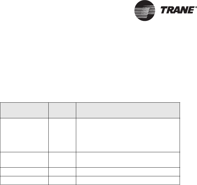
Table 16. Inputs and outputs
Ty p e Number Description
Universal inputs 12 Dry-contact binary, thermistor,
0–20 mA, 0–10 Vdc, linear resistance.
The first four inputs can be used
directly with resistance temperature
detectors (RTDs).
Static pressure
input
1 Differential pressure sensor, 5 Vdc,
0–5 in. wc
Binary outputs 6 Powered relay contacts, 6 VA at 24 Vac
Analog outputs 6 0–10 Vdc or 0–20 mA