Understanding bindings
BAS-APG001-EN 133
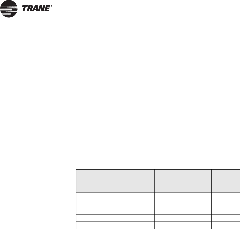
The address table consists of the following elements (refer to column
headings in
Table 38):
• Use Domain at Index: This number represents a pointer or reference
to a table entry in the Domain table. For Trane devices, the value at
index (or row) 0 will be a decimal 17.
• Group Number or Subnet Address field: The function varies
depending on the binding type. For group bindings, the group number
is stored here. For subnet/node bindings, the subnet address is stored
here.
• Group Member at Node Address field: This varies depending on the
binding type. The group member specifies a unique number for each
member of a group binding.
• Group Size field: This specifies the total number of members in the
group binding.
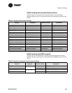
The address table in Table 38 shows a subnet/node binding at index 0,
which lists a device at DSN 17-1-8 as the destination. And it shows that
the device is the second member of Group 1, which has a total of three
members.
Table 38. Address table
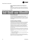
Designing bindings
On a LonWorks job, binding connections should be designed and
documented just like wiring connections are designed and documented on
shop drawings. Follow these rules, limits, and the methodology provided
when designing bindings:
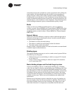
Binding rules and limits
1. Bindings can be made only between NVs that have the same network
variable type (SNVT or UNVT).
For example, nvoSpaceTemp is of type SNVT_temp_p and nviSpaceT-
emp is also of type SNVT_temp_p, so these two variables can be
bound. Rover takes care of matching network variable types for you,
but during design, this fundamental rule should be kept in mind.
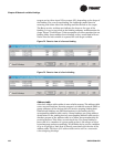
2. Unique subnet/node binding types consume an address table entry on
the sending device only.
Addr
index
Binding
type
Use
Domain at
Index
Group
Number or
Subnet
Address
Group
Member of
Node
Address Group Size
0 subnet/node 0 1 8 n/a
1 group 0 1 2 3
2 unbound
3 unbound
14 unbound


