


Wiring inputs and outputs
BAS-APG001-EN 65
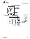
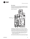
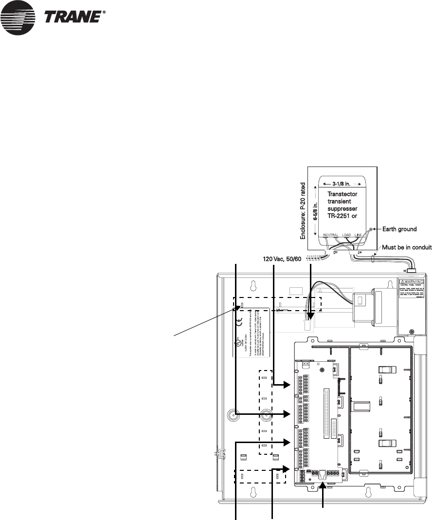
Wire routing
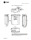
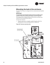
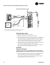
Figure 32 shows how to route input/output wires through the enclosure.
It also shows the locations of wire-tie brackets. See Figure 27 on page 57
for knockout locations and dimensions. Metal conduit may be required by
local codes when running input/output wires.
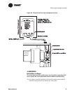
Figure 32. Wire routing
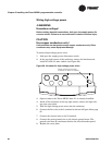
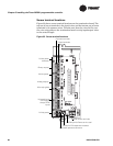
Providing low-voltage power for inputs and outputs
The Tracer MP581 controller can provide low-voltage power to inputs and
outputs.
Figure 33 on page 66 shows the location of the low-voltage screw
terminals on the termination board. The following limitations apply:
• Four 24 Vdc screw terminals supply a total of up to 250 mA of power.
• Two 24 Vac screw terminals supply a total of up to 17 VA of power.
The 50
VA of available power supplies both the 24 Vac screw
terminals and binary outputs.
Note that more than one input or output can receive power from a given
screw terminal. The only limitation is the total amount of power supplied.
Brackets for wire
ties (9 locations)
Recommended
communication wire route