


Chapter 5 Installing the Tracer MP581 programmable controller
70 BAS-APG001-EN
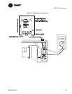
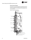
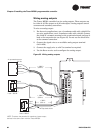
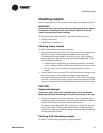
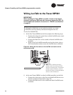
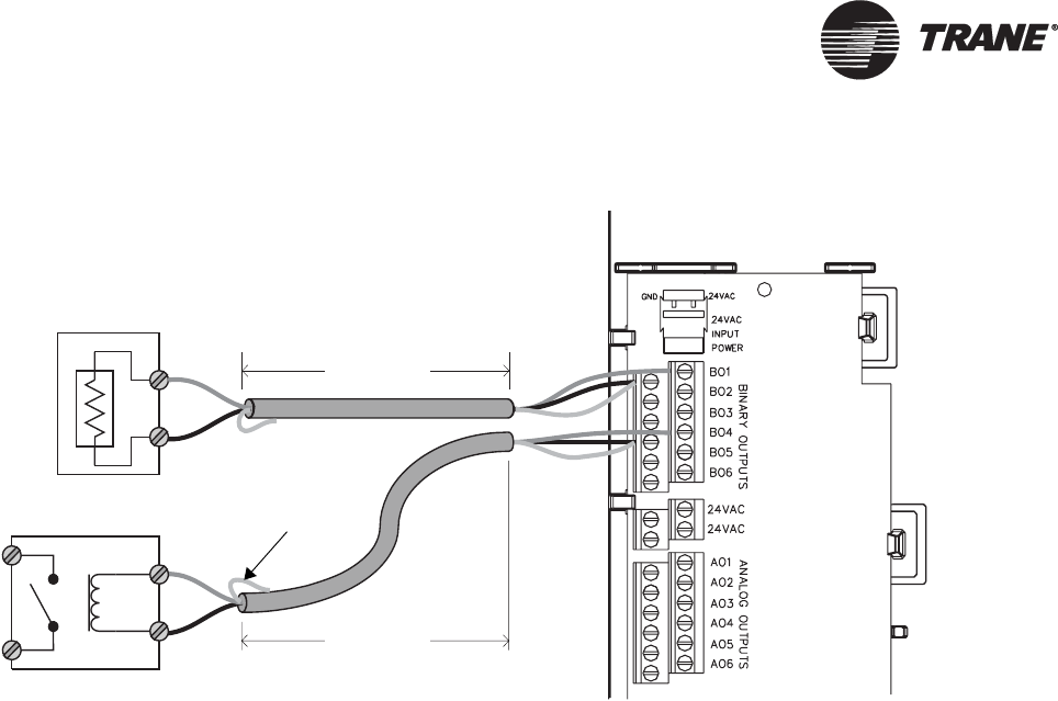
Figure 36. Wiring binary outputs
Checking binary inputs
To check binary inputs for proper operation:
1. Make sure that the sensor is connected and closed.
2. Set the multi-meter to measure Vac, then measure the voltage across
the input connections at the signal and common screw terminals.
The measured voltage should be less than 0.1 Vac. If the voltage is
greater than this, the input readings may change erratically.
3. Set the multi-meter to measure Vdc, then measure the voltage across
the input at the signal and common screw terminals.
The measured voltage should be less than 0.1 Vdc. If the voltage is
greater than this, the input readings may be offset.
CAUTION
Equipment damage!
Continue to step 4 only if you completed steps 2 and 3 successfully.
Measuring resistance may damage the meter if the voltage is too high.
4. Set the multi-meter to measure resistance. If you completed steps 2
and 3 successfully, measure the resistance across the input.
The resistance should be less than 200 Ω when the binary input is
closed and greater than 1 kΩ when it is open.
Powered output
< 1000 ft
(300 m)
< 1000 ft
(300 m)
Pilot relay
24 Vac coil
Signal
Common
Signal
Common
Tape back shield
NOTE: To reduce the potential for transients, locate output
devices in the same room with the Tracer MP581.