


System termination diagrams
BAS-APG001-EN 35
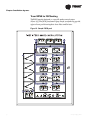
The wiring between a Tracer MP581 and the FSCS is non-supervised and
power limited. Additional requirements are:
• Tracer MP581 and FSCS must be in the same room.
• Wiring between the Tracer MP581 and FSCS must be in conduit.
• Wiring distance cannot exceed 20 ft.
• Wire must be #18 AWG.
The number of wires needed between the Tracer MP581(s) and the FSCS
is determined by the total number of zones and manual override switches
at the FSCS. Multiple Tracer MP581 panels may be required to monitor
and control the FSCS. One Tracer MP581 controls the trouble LED and
the Sonalert audible alarm of the FSCS, as well as supplying 24 Vac
power to operate the lamp test relay(s).
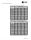
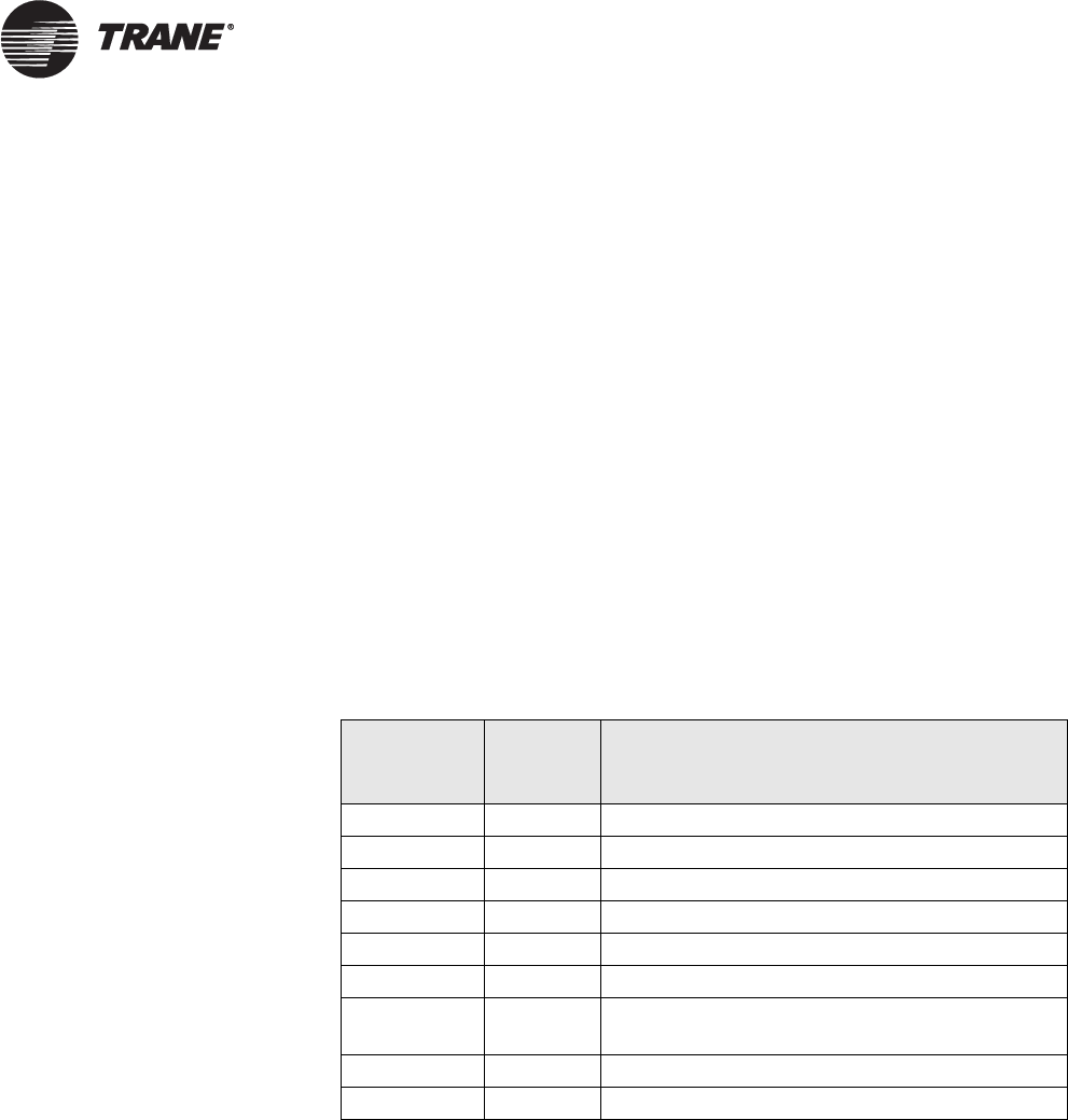
Table 9 shows wires for a typical Tracer MP581 that controls the FSCS
trouble LED and the Sonalert audible alarm.
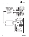
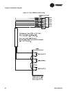
Figure 14 on page 36 shows Tracer MP581 to FSCS wiring.
Table 9. Wires for a Tracer MP581 that control FSCS trouble LED and
Sonalert alarm
Cables per
Tracer
MP581
Ty pe of
wiring
Function
1–22 24 Vac Binary output to light LED on FSCS
1 24 Vac Binary output controlling trouble LED
1 24 Vac Binary output controlling Sonalert alarm LED
1 24 Vac Binary output controlling Sonalert alarm
1 24 Vac “Hot” power wire for the FSCS lamp test relays
1 24 Vac Common
1–36 22 Vdc Two binary input wires per FSCS switch (up to
36 switches per Tracer MP581)
1 22 Vdc Binary input wire for lamp test signal
1 22 Vdc Common