


Chapter 4 Installing the Tracer Summit BMTX BCU
48 BAS-APG001-EN
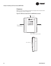
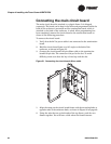
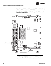
Connecting the main circuit board
The main circuit board is attached to a plastic frame. It is shipped
separately. The board can be kept in the office and programmed while the
back of the enclosure is mounted and the termination board, which is
attached to the back of the enclosure, is wired. After programming has
been completed, connect the circuit board to the termination board as
shown in the following procedure.
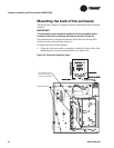
To connect the circuit board:
1. Verify that the 24 Vac power cable is not connected to the termination
board.
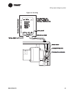
2. Hold the circuit board frame at a 90° angle to the back of the
enclosure, as shown in
Figure 21.
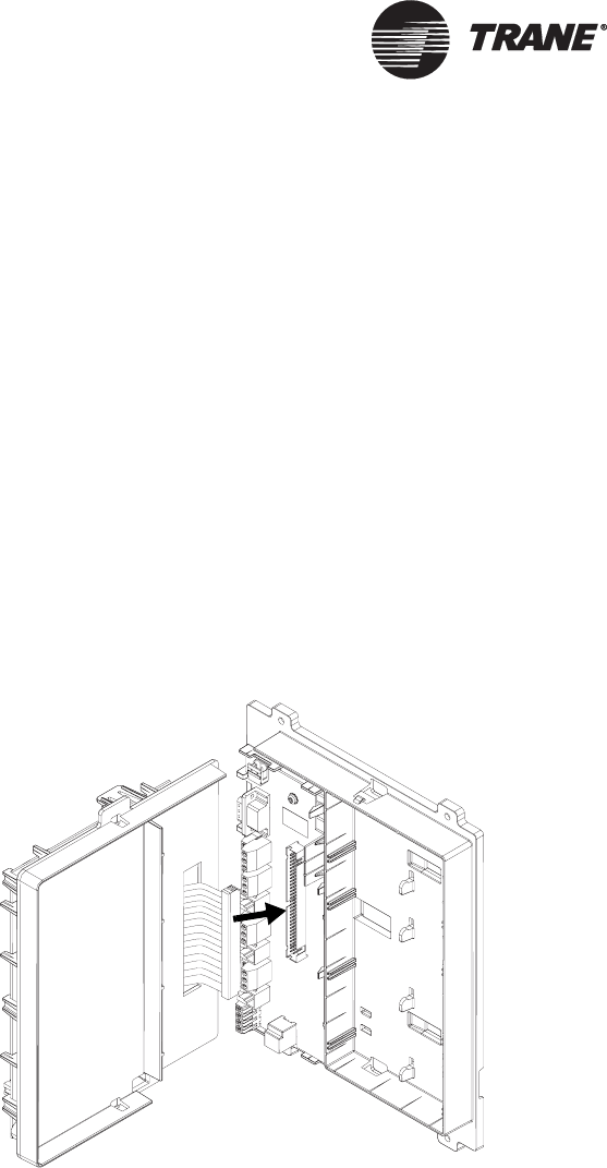
3. Connect the circuit board’s 60-pin ribbon cable to the termination
board’s 60-pin slot. The connector is keyed to the slot. To avoid
difficulty, make sure that the key is lined up with the slot.
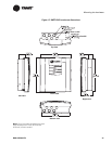
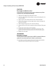
Figure 21. Connecting the circuit board ribbon cable
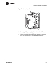
1. Align the snaps on the circuit board frame with the mounting locks at
opposite ends of the enclosure back, as shown in
Figure 22 on page 49.
2. Using the tabs that are at both ends of the top frame, push the two
frames together. You will hear a click when the frames connect.