


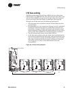

I/O bus wiring
BAS-APG001-EN 91
I/O bus wiring
The EX2 communicates with the Tracer MP581 and up to three other
EX2 modules on an IEEE-485 link. This link must be a daisy chain. Typi
-
cally, the Tracer MP581 is at one end of the daisy chain, but any device
can be at the ends of the link (
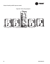
Figure 48 and Figure 49 on page 92).
Wiring for the I/O bus must meet the following requirements:
• All wiring must be in accordance with the National Electrical Code
and local codes.
• Recommended wire is low-capacitance, 22-gauge, Level 4, unshielded,
twisted-pair. Existing sites that have already been wired with low-
capacitance, 18-gauge, shielded, twisted pair with stranded, tinned-
copper conductors (Trane-approved, purple-jacketed wire) don't have
to be rewired. This shielded wire will work if properly terminated.
• Total I/O wiring length cannot exceed 1000 ft (300 m).
• At the first three modules, splice the shield with the shield from the
next section of communication-link wiring, and tape the shield to pre
-
vent any connection to ground. At the final module on the end of the
daisy chain, terminate the shield as shown in
Figure 48. Note that
you can use one, two, three, or four EX2 modules with each
Tracer
MP581.
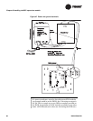
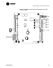
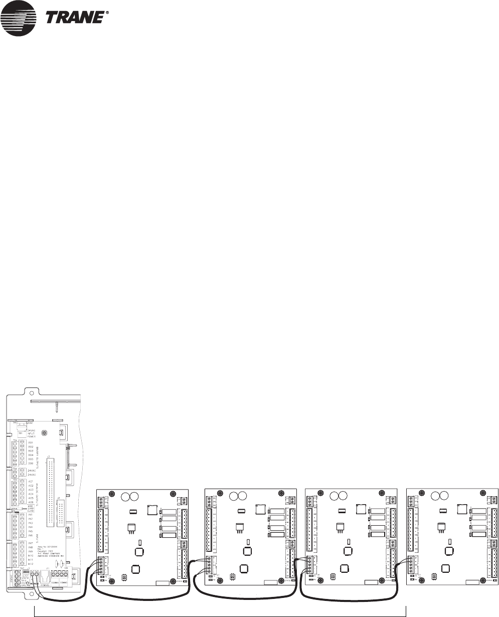
Figure 48. I/O bus wiring example 1
Tracer MP581
EX2 EX2 EX2
EX2
Up to 1000 ft (300 m)