


Custom bindings
BAS-APG001-EN 123
Custom bindings
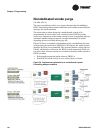
A distinction is made between FSCP and mechanical system control in
this section. While smoke control panel processing is predictable,
mechanical system processing (actuators, feedback validation) is
unknown. It is limited to approximately five smoke control zones based
on the UUKL-approved smoke control panel. Because the number and
application of each MP581 and EX2 modules is unknown, the mechanical
system will be represented as a “cloud.”
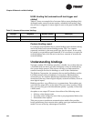
The recommended smoke control system design is to have one MP580/581
assigned as the “communication clearing house” or hub. It may be
necessary to use two or more hubs, one for panel control and another
hub(s) for the mechanical system. This design will simplify the binding
creation process and makes the system more scalable. For more
information regarding the limitations placed on custom binding and
recommendations regarding custom binding design, see
“Understanding
bindings” on page 130.
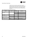
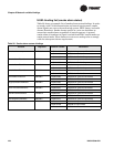
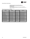
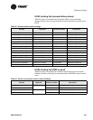
The bindings and variables shown in Table 31–Table 37 were those used
in the tested UUKL system to send information between MP580s. The
system programmer can use whatever bindings and variables are
necessary.
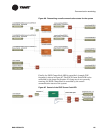
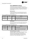
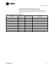
UUKL binding list (watchdog communication)
“Trouble signals and their restoration to normal shall be annunciated
within 200 seconds of the occurrence of the adverse condition, fault, or the
restoration to normal.” (UL-864: 49.2.b)
As there is no built in means of verifying inter-MP581 communication
status, a programmed solution must be used. While a network variable
“heartbeat” can be used to verify status, it can take up to 300 seconds for
a communication failure to be noticed. This solution would fail to meet
the requirement given in previous paragraph. The tested solution is
based on a “watchdog” style where a continuously changing network
variable triggers a timer every time it changes state. As long as the timer
never expires, it is assumed that the two devices are communicating. In
this fashion, a communication failure can be annunciated within 60
seconds.
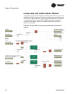
Table 31 on page 124 shows an example of a custom binding list. One
group binding binds MP580-2, which is the hub, to all other MP581s (for
an explanation of group bindings, see
“Understanding bindings” on
page 130). The “watchdog” signal sent to the group is used by each
receiver to confirm communications from the hub unit. The hub unit is
able to validate communications from each of other MP581s using their
individual “watchdog” signals. These bindings are point-to-point based.
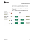
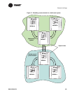
There may be two hubs in the system, one used with the FSCP and other
within the mechanical system. The need for a second hub will be driven
by the size of the mechanical system involved.
Figure 71 on page 125
illustrates watchdog communication between MP581s in a hub-based
system.