


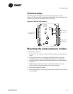
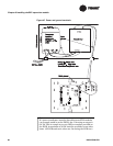

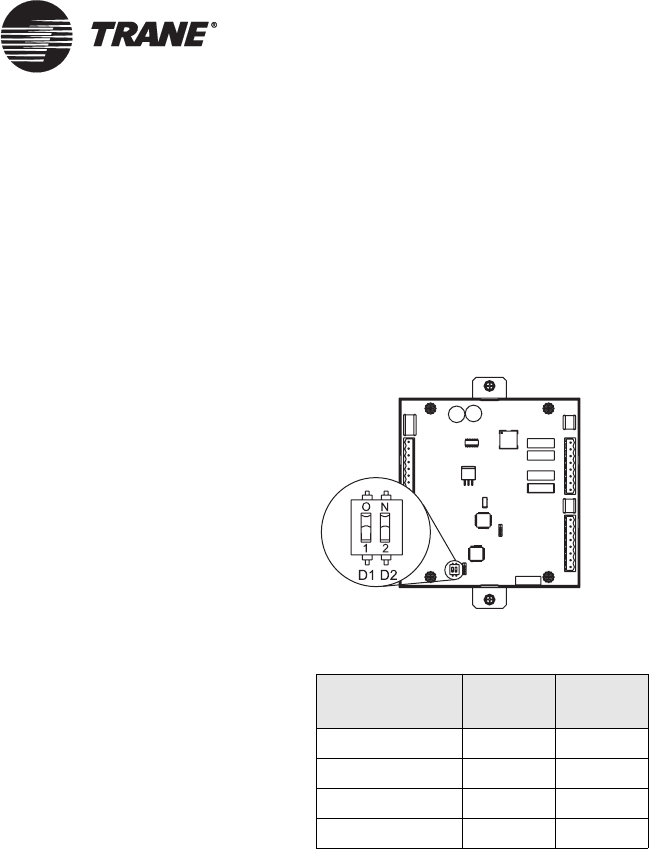
Setting the I/O bus addresses
BAS-APG001-EN 93
Setting the I/O bus addresses
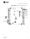
Each EX2 on the link with the Tracer MP581 must have a unique
address. Configure the address using the DIP switches on the EX2 circuit
board (
Figure 50). Table 23 shows the DIP switch settings for expansion
modules 1 through 4.
Figure 50. DIP switch on board
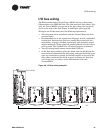
Input/output terminal wiring
All input/output terminal wiring for the EX2 module must meet the fol-
lowing requirements:
• All wiring must be in accordance with the National Electrical Code
and local codes.
• Use only 18 AWG twisted-pair wire with stranded, tinned-copper
conductors.
• Binary output wiring must not exceed 20 ft (6.1 m) and must be in
conduit.
• Binary input wiring must not exceed 20 ft (6.1 m) and must be in
conduit.
• Analog and 24 Vdc output wiring distances depend on the specifica-
tions of the receiving unit. Use shielding for analog and 24 Vdc
outputs.
• Do not run input/output wires in the same wire bundle with ac-power
wires.
Table 23. EX2 DIP switch settings
EX2 module D1 D2
1 Off Off
2 Off On
3 On Off
4 On On