


1-2 Part III
Part III Model 6600
Teledyne Analytical Instruments
Analytical accuracy of the equipment is better than 2% when it has been
calibrated with an oil identical to that being measured. Reproducibility of
analysis equals or exceeds that of any known laboratory or analytical method.
When calibrated in a range of 0-10 ppm, changes as little as 0.1 ppm are detected
(1% sensitivity).
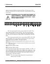
2.0 The Method of Analysis
The following description follows the course of an optical beam, emitted
from a source lamp in the SOURCE MODULE, passed through the sample to
be analyzed in the SAMPLE CELL, and received (through optical filters),
converted to pulses of electrical energy, and further conditioned, in the
DETECTOR MODULE. The result is separate pulses which are compared in
the control/analysis unit to reveal the measurable difference between optical
absorption of the sample at a selected wavelength (determined by the
MEASURING optical filter) and a zero-absorption condition (set by the
REFERENCE optical filter). The magnitude of that difference represents the
concentration of the component of interest in the sample.
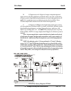
2.1 The Optical Bench
Energy from a Mercury Line lamp, used as a source, is optically focused
through a folded path through a sample cell onto a photo detector. In front of
the detector is a motor-driven filter disc containing two optical filters mounted
180 degrees apart which alternately and continuously rotate into and out of the
light beam. Sample flows continuously through the sample cell and absorbs
optical energy at various wavelengths in accordance with its composition.
The analyzer monitors two of the wavelengths: a measuring wavelength
selected where the components of interest has a characteristic spectral peek
absorbance, and a reference wavelength (where oil does not absorb) utilized to
provide stability by detecting extraneous phenomena such as turbidity, cell
window deposits, unequal optical component aging, etc. The reference wave-
length is also sometimes selected at a point where automatic compensation is
attained for interference from other sample components.
2.2 The Photometer Amplifier
The photo detector converts the photo energy impinging on it to electrical
energy. The magnitude of the photo energy pulses which strike the detector is
related to absorbance by the sample and the properties of the optical filters.