


3 Operation Model 6600
3-30 Part I
Teledyne Analytical Instruments
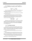
Sel rng to set appl:
—> Ø1 Ø2 Ø3 <—
Use the UP/DOWN switch to increment/decrement the range number to
01, 02, 03, or CAL, and Enter.
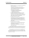
Gas Name **********
FR:Ø TO:1Ø %
Use the UP/DOWN switch to increment the respective parameters as
desired, and Enter to move to the next. On the last field %/ppm Enter to accept
the values and return to range selection menu. (See note below.) Repeat for each
range you want to set.
Note: The ranges must be increasing from low to high, for example,
if Range 1 is set to 0–10 % and Range 2 is set to 0–100 %, then
Range 3 cannot be set to 0–50 % since that makes Range 3
lower than Range 2.
Ranges, alarms, and spans are always set in either percent or ppm units, as
selected by the operator, even though all concentration-data outputs change
from ppm to percent when the concentration is above 9999 ppm.
Note: When performing analysis on a fixed range, if the concentra-
tion rises above the upper limit as established by the operator
for that particular range, the output saturates at 1 V dc (or 20
mA). However, the digital readout and the RS-232 output
continue to read regardless of the analog output range.
To end the session, send:
st<enter>
st<enter>
to the analyzer from the computer.
3.8.2 The Curve Algorithm Screen
The Curve Algorithm is a linearization method. It provides from 1 to 9
intermediate points between the ZERO and SPAN values, which can be normal-
ized during calibration, to ensure a straight-line input/output transfer function
through the analyzer.
Each range is linearized individually, as necessary, since each range will
usually have a totally different linearization requirement.
To linearize the ranges, you must first perform the four steps indicated at
the beginning of section 3.8 Programming. You will then be in the second
System menu screen.