1-18 Part III
Part III Model 6600
Teledyne Analytical Instruments
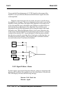
Coarse and the Fine adjustments to 2.5 VDC should set the output of the
amplifier to zero provided the Measure and the Reference signals have the
same magnitude.
When the control unit enters the zero mode, the micro controller drops
the amplifier to a low gain. The coarse adjustment is first used to zero out the
amplifier on this gain. When the output of the amplifier is reasonably close
to zero, the amplifier goes to the highest gain. Whatever residual offset was
left from the coarse adjustment is now magnified. Now with the coarse
adjustment fixed, the Fine adjustments tries to bring the output of the ampli-
fier back to zero. When the high gain offset is close to zero, the micro con-
troller freezes the Fine and the Coarse adjustments and proceeds to read the
residual offset with the ADC. It goes through all of the ten gains available,
thus the micro controller stores the offset of each gain, so that later they can
be subtracted from the readings. This period of time is called the Software
zero and it takes about 70 seconds to be finished.
3.8.2 Signal Failure Alarm
System contacts are activated when the reference voltage as measured at the
junction of R3 and R4 of the amplifier board, has fallen below 0.50 millivolts
The VFD display will show the following message:
Detector Fail Check the
Detector signal
F adj
C adj
M sig
R sig
+2.5
U4


