


Part I: Control Section Maintenance 4
Part I: 4-3
Teledyne Analytical Instruments
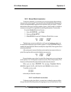
Preamp
0OK
1 Zero too high
2 Amplifier output doesn't match test input
3 Both Failed
>3 Call factory for information
Detector
0OK
1 Failed (open filament, short to ground, no
power.)
2 Unbalance (deterioration of filaments, blocked
tube)
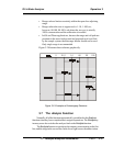
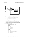
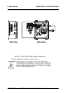
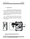
4.3 Major Internal Components
All internal components are accessed by unbolting and swinging open
the front cover, as described earlier. The major internal component locations
are shown in Figure 4-2, the cell block is illustrated in Figure 3-2, and the
fuse receptacle is shown in Figure 3-3
The 6600 contains the following major internal components:
• Customer Interface PCB (Power Supply on bottom surface)
• Preamp PCB (Contains Microprocessor)
• Front Panel PCB (Contains Displays)
5 digit LED meter
2 line, 20 character, alphanumeric, VFD display
See the drawings in the Drawings section in back of this manual
for details.
For Optical/Detector Alignments, refer to parts II or III of this manual