


Oil in Water Analyzer Part I: Control Section
Part I: 2-3
Teledyne Analytical Instruments
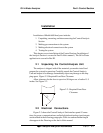
Fuse Installation: The fuse holders accept 5 x 20 mm, 4.0 A, T
type (slow blow) fuses. Fuses are not installed at the factory. Be sure to
install the proper fuse as part of installation (See Fuse Replacement in
chapter 4, maintenance.)
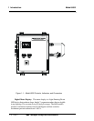
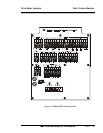
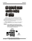
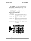
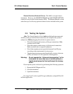
Analog Outputs: There are eight DC output signal connectors on
the ANALOG OUTPUTS terminal block. There are two connectors per
output with the polarity noted. See Figure 2-5.
The outputs are:
0–1 V dc % of Range: Voltage rises linearly with increasing sample con-
centration, from 0 V at 0% to 1 V at 100%. (Full
scale = 100% programmed range.)
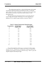
0–1 V dc Range ID: 0.25 V = Range 1, 0.5 V = Range 2, 0.75 V =
Range 3.
4–20 mA dc % Range: (-M Option) Current increases linearly with increas-
ing sample concentration, from 4 mA at 0% to 20
mA at full scale 100%. (Full scale = 100% of
programmed range.)
4–20 mA dc Range ID: (-M Option) 8 mA = Range 1, 12 mA = Range 2,
16 mA = Range 3.
Figure 2-5: Analog Output Connections
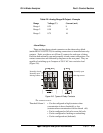
Examples: