


Oil in Water Analyzer Part II: Analysis Unit
Part II: 2-1
Teledyne Analytical Instruments
Installation
Installation of the Model 6600 Photometric Analyzer includes:
1. Unpacking
2. Mounting
3. Fluid connections
4. Electrical connections
5. Testing the system.
2.1 Unpacking the Analyzer
The analyzer is shipped with all the materials you need to install and
prepare the system for operation. Carefully unpack the analyzer and inspect
it for damage. Immediately report any damage to the shipping agent.
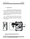
2.2 Installing and Connecting the Analyzer
Without Temperature Control, the system must be installed in an area
where the ambient temperature is not permitted to drop below 32°F freezing nor
rise above 122°F (0-50°C).
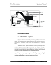
Regardless of configuration, the system must be installed on a level surface
with sufficient space allocated on either side for personnel and test equipment
access. Subject to the foregoing, the system should be placed as close to the
sample point as possible and bolted to its supporting surface. A waterproof
mastic should be liberally applied to the under surfaces of all four supporting legs
of the cubicle system before placing it in position and bolting it in place.
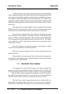
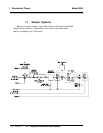
2.2.1 User Connections
All user connections are around the periphery of the equipment
panel (or cubicle) and appear in the outline diagram in the back of the manual.