


Oil in Water Analyzer Part I: Control Section
Part I: 2-1
Teledyne Analytical Instruments
Installation
Installation of Model 6600 Analyzers includes:
1. Unpacking, mounting, and interconnecting the Control/Analysis
Section
2. Making gas connections to the system
3. Making electrical connections to the system
4. Testing the system.
This chapter covers installation of the Control Section. (Installation of
the Analysis Section is covered in Part II of this manual.) The Oil in Water
application is covered in Part III.
2.1 Unpacking the Control/Analysis Unit
The analyzer is shipped with all the materials you need to install and
prepare the system for operation. Carefully unpack the Control/Analysis
Unit and inspect it for damage. Immediately report any damage to the ship-
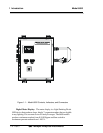
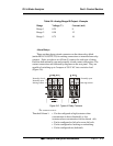
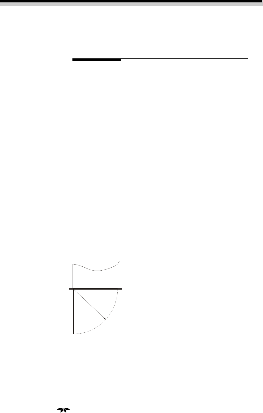
ping agent. Figure 2-2: Required Front Door Clearance
Allow clearance for the door to open in a 90-degree arc of radius 15.5
inches. See Figure 2-2.
Figure 2-2: Required Front Door
Clearance
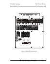
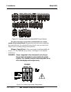
2.2 Electrical Connections
Figure 2-3 shows the Control/Analysis Unit interface panel. Connec-
tions for power, communications, and both digital and analog signal outputs
are described in the following paragraphs. Wire size and maximum length
data appear in the Drawings at the back of this manual.
1
5
.
5
”