


1-20 Part III
Part III Model 6600
Teledyne Analytical Instruments
surface. A waterproof mastic should be liberally applied to the under sur-
faces of all four supporting legs of the cubicle system
before placing it in
position and bolting it in place.
4.1 User Connections
All user connections are located around the periphery of the equipment
panel (or cubicle) and are shown in the Outline Diagram.
4.1.1 Electrical Power Connections
The system requires a 1 KW supply of 115 VAC, single-phase power.
Power connections are made inside the control unit. Refer to the Intercon-
nection Diagram. The electrical power service must include a high-quality
ground wire. A high-quality ground is defined as having zero potential
difference when measured to the power line neutral.
4.1.2 Compressed Air Supply
The system requires a supply of compressed air at 80-120 psig.
NOTE: The air supply must be oil free. As a precaution, however,
the air pressure line should contain a filter(s) to remove any traces of oil,
supplied and maintained by the customer.
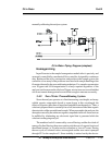
4.1.3 Sample Connection
The sample water input (see Flow Diagram) is connected at the manual
valve input. A flowrate of 1 gallon/minute, minimum, is recommended.
Maximum flow is governed by the impedance of the delivery system.
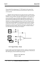
4.1.4 Signal and Alarm Output Connections
Signal and alarm output connections are made inside the control unit to
terminal blocks mounted on the interface board. Refer to chapter 2 of
control unit part of the manual.
NOTE: Signal circuit resistance, including accessory devices, must not
exceed 1000 ohms. The alarm contact circuit must not draw more than 3
amperes at 250 VAC (None inductive), or 30VDC.