


2 Installation Model 6600
2-2: Part I
Teledyne Analytical Instruments
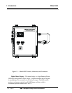
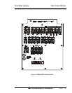
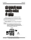
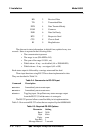
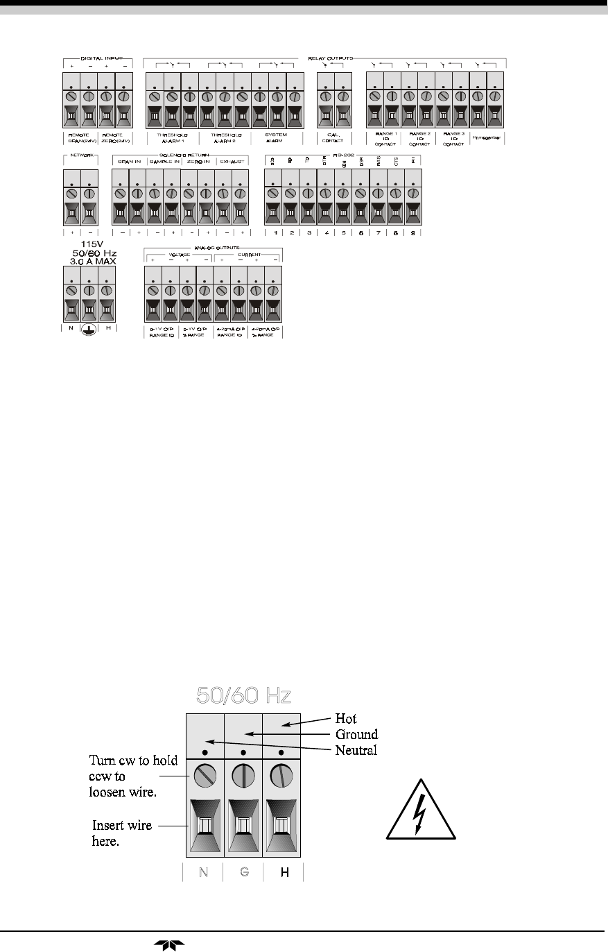
Figure 2-3: Interface Panel of the Model 6600 Control Section
For safe connections, ensure that no uninsulated wire extends
outside of the terminal blocks. Stripped wire ends must insert completely
into terminal blocks. No uninsulated wiring should come in contact with
fingers, tools or clothing during normal operation.
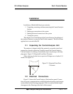
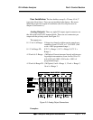
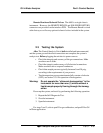
Primary Input Power: The power supply in the Model 6600 will
accept a 115 Vac, 50/60 Hz power source. See Figure 2-4 for detailed
connections.
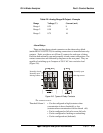
DANGER: Power is applied to the instrument's circuitry as
long as the instrument is connected to the power
source. The standby function switches power on or
off to the displays and outputs only.
Figure 2-4: Primary Input Power Connections
115VAC