


Oil in Water Analyzer Maintenance 3
Part II 3-3
Teledyne Analytical Instruments
2. Check the UV source.
NOTE: Be sure to wear UV filtering eye goggles.
3. Check the solenoid valves.
3.5 Service Procedures and Adjustments
3.5.1 Electronics
TAI aligns the system’s electronics. However, you may
need to touch up the circuitry, using the following procedure.
Equipment Required:
Oscilloscope (dual trace is preferred, but not required) To observe
oscilloscope test points switch the vertical input selector of the scope to DC.
Switch to AC to observe the demodulator switch signals.
DVM (Digital Voltmeter)
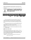
3.5.2 Power Supply Test Points
Measure +15 volt ±1 volt DC and -15 volt ±1 volt DC on the differential
power supply PC board in the control unit. Refer to the power supply schematic
in the back of the manual to identify the power supply test points, or section 3.6
in this chapter.
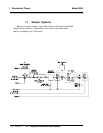
3.5.3 Setup of the Signal Processing Front-End
Amplifiers
Fill the sample cell with air or a stable fluid, such that the photo
energy that strikes the detector is constant. A stable fluid is distilled or tap
water. This step may be omitted when the system is stable in its present
state.