


ii: Part III
Model 6620 Oil in Water Analyzer
Teledyne Analytical Instruments
Table of Contents
1.0 Introduction .................................................................... 1-1
2.0 The Method of Analysis ................................................. 1-2
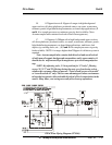
2.1 The Optical Bench ......................................................... 1-2
2.2 The Photometer Amlifier ................................................ 1-2
2.3 The Automatic Zero System........................................... 1-4
2.4 Piping Schematic - B71046-0 ........................................ 1-4
2.5 Zero Correction for Clean Background Stream .............. 1-6
2.6 Zero Correction for High Background Stream ................ 1-7
3.0 System Description ........................................................ 1-8
3.1 Photommeter ................................................................. 1-9
3.1.1 Source Module ........................................................ 1-9
3.1.2 Sample Cell ............................................................. 1-9
3.1.3 Detector Module ...................................................... 1-9
3.1.4 Control Unit .............................................................. 1-10
3.3 Electrical Connections ................................................... 1-11
3.4 The Sampling System.................................................... 1-11
3.4.1 Sample Water Preconditioning System .................. 1-11
3.4.2 Zero Water Preconditioning System ....................... 1-13
3.4.3 The Automatic Sample Cell Cleaning System ....... 1-14
3.5 The Signal Outputs ........................................................ 1-16
3.6 Recorder Requirements ................................................. 1-16
3.7 The Process Alarm System............................................ 1-17
3.8 The Amplifier PCB ......................................................... 1-17
3.8.1 Auto Zero Circuit .................................................... 1-17
3.8.2 Signal Failure Alarm .............................................. 1-18
4.0 Installation...................................................................... 1-19
4.1 User Connections .......................................................... 1-19
4.1.1 Electrical Power Connections ................................ 1-20
4.1.2 Compressed Air Supply ......................................... 1-20
4.1.3 Sample Connections ............................................. 1-20
4.1.4 Signal & Alarm Output Connections ...................... 1-20