


17
GB
Caution:
Place a wet towel on the refrigerant service valve before heating the brazed •
section to keep the temperature of the valve from exceeding 120 ˚C.
Direct the ame away from the wiring and metal sheets inside the unit •
to prevent heat damage.
Caution:
Do not vent R410A into the atmosphere.•
R410A is a Fluorinated Greenhouse gas, covered by the Kyoto •
Protocol, with a Global Warming Potential (GWP) = 1975.
Refrigerant pipe connection•
This product includes connecting pipes for front piping and bottom post-
piping. (Refer to [Fig.10.2.2])
Check the liquid/gas piping dimensions before connecting the refrigerant pipe.
Refer to item 9.2 Refrigerant piping system for piping dimensions.
Make sure that the refrigerant pipe is not touching other refrigerants pipes,
unit panels, or base plates.
Be sure to use non-oxidative brazing when connecting pipes.
Be careful not to burn the wiring and plate when brazing.
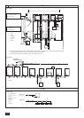
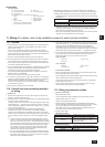
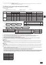
<Refrigerant piping connection examples>
[Fig.10.2.2] (P.7)
<A> Front pipe routing <B> Bottom pipe routing
<C> Included with outdoor unit
A
Gas pipe (eld supply required)
B
Liquid pipe (eld supply required)
C
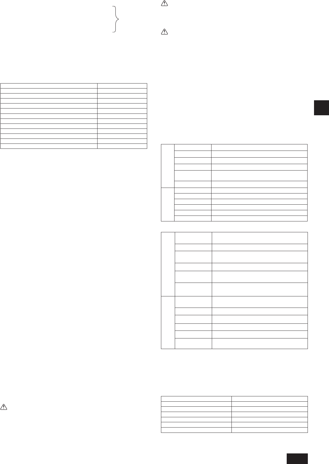
Shape
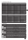
Front pipe routing•
Liquid
side
P200,P250,EP200
Use the included connecting pipe d to connect.
P300
Use the included connecting pipe 4 and e to connect.
P300*2 *3
Use the included connecting pipe e to connect.
EP250, EP300
Use the included connecting pipe 5 and f to connect.
EP250*1, EP300*2 *3
P350, P400
Use the included connecting pipe 7 and f to connect.
P400*3, P450
Use the included connecting pipe f to connect.
Gas
side
P200
Use the included elbow 1 to connect.
EP200
Use the included elbow 2 and connecting pipe 9 to connect.
P250, EP250, P300
Use the included elbow 2 and connecting pipe 0 to connect.
EP300
Use the included elbow 3 and connecting pipe a to connect.
P350, P400
Use the included elbow 2 and connecting pipe b to connect.
P450
Use the included elbow 3 to connect.
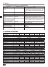
Bottom pipe routing•
*1 Over 90m
*2 Over 40m
*3 In the case the unit is used in combination with other outdoor units.
*4 EP650YSJM-A : Use the included connecting pipe 6 , 8, and c to connect to the
twinning kit.
*5 EP700YSJM-A1 : Use the included connecting pipe 6 to connect to the twinning kit.
*6 EP750YSJM-A1 : Use the included connecting pipe 6 to connect to the twinning kit.
(*4~*6: Refer to item 9.2.)
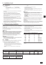
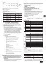
Satisfy the minimum insertion depth in the table below when expanding on-site piping
Pipe diameter (mm) Minimum insertion depth (mm)
5 or more less than 8 6
8 or more less than 12 7
12 or more less than 16 8
16 or more less than 25 10
25 or more less than 35 12
35 or more less than 45 14
After evacuation and refrigerant charging, ensure that the handle is fully •
open. If operating with the valve closed, abnormal pressure will be imparted
to the high- or low-pressure side of the refrigerant circuit, giving damage to
the compressor, four-way valve, etc.
At the
conditions
below:
<Example>
Indoor 1: 125 A: ø12.7 40 m a: ø9.52 10 m
2: 100 B: ø9.52 10 m b: ø9.52 5 m
3: 40 C: ø9.52 15 m c: ø6.35 10 m
4: 32 D: ø9.52 10 m d: ø6.35 10 m
5: 63 e: ø9.52 10 m
The total length of each liquid line is as follows:
ø12.7: A = 40 = 40 m
ø9.52: B + C + D + a + b + e = 10 + 15 + 10 + 10 + 5 + 10 = 60 m
ø6.35: c + d = 10 + 10 = 20 m
Therefore,
<Calculation example>
Additional refrigerant charge
= 40 × 0.12 + 60 × 0.06 + 20 × 0.024 + 3.5 = 12.4 kg
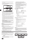
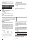
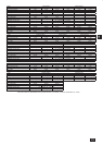
Value of α
Total capacity of connecting indoor units
α
Models ~ 80 2.0 k
g
Models 81 ~ 160 2.5 k
g
Models 161 ~ 330 3.0 k
g
Models 331 ~ 390 3.5 k
g
Models 391 ~ 480 4.5 k
g
Models 481 ~ 630 5.0 k
g
Models 631 ~ 710 6.0 k
g
Models 711 ~ 800 8.0 k
g
Models 801 ~ 890 9.0 k
g
Models 891 ~ 1070 10.0 k
g
Models 1071 ~ 1250 12.0 k
g
Models 1251 ~ 14.0 k
g
10.2. Precautions concerning piping
connection and valve operation
Conduct piping connection and valve operation accurately and carefully.•
Removing the pinched connecting pipe•
When shipped, a pinched connecting pipe is attached to the on-site liquid
and gas valves to prevent gas leakage.
Take the following steps 1 through 4 to remove the pinched connecting
pipe before connecting refrigerant pipes to the outdoor unit.
1 Check that the refrigerant service valve is fully closed (turned clockwise
all the way).
2 Connect a charging hose to the service port on the liquid/gas refrigerant
service valve, and extract the gas in the pipe section between the
refrigerant service valve and the pinched connecting pipe.
3 After vacuuming gas from the pinched connecting pipe, sever the
pinched connecting pipe at the location shown in [Fig.10.2.1] and drain
the refrigerant.
4 After completing 2 and 3 heat the brazed section to remove the
pinched connecting pipe.
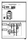
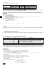
[Fig. 10.2.1] (P.7)
<A> Refrigerant service valve (liquid side/brazed type)
<B> Refrigerant service valve (gas side/brazed type)
A
Shaft
Fully closed at the factory, when connecting the piping, and when
vacuuming. Open fully after these operations are completed.
<When opening>
• Turn the shaft counterclockwise with a hexagonal wrench.
• Turn around the shaft until it stops.
<When closing>
• Turn the shaft clockwise with a hexagonal wrench.
• Turn around the shaft until it stops.
B
Shaft
Fully closed at the factory, when connecting the piping, and when
vacuuming. Open fully after these operations are completed.
<When opening>
• Turn the shaft counterclockwise.
• Turn around the shaft until it stops.
<When closing>
• Turn the shaft clockwise.
• Turn around the shaft until it stops.
C
Stopper pin
Prevents the shaft from turning 90° or more.
D
Service port
Available for gas venting of the pinched connecting pipe, or vacuuming in the
refrigerant pipes on the site.
E
Cap
Remove the cap before operating the shaft. Be sure to return it to the original
position after completing the operation.
F
Pinched connecting pipe severing portion
G
Pinched connecting pipe brazing portion
Warning:
The sections between the refrigerant service valves and the pinched •
connecting pipes are lled with gas and refrigerant oil. Extract the gas
and refrigerant oil in the above-mentioned pipe section before heating
the brazed section to remove the refrigerant service valve pinched
connecting pipe.
- If the brazed section is heated without rst extracting the gas and
refrigerant oil, the pipe may burst or the pinched connecting pipe may blow
off and ignite the refrigerant oil, causing serious injury.
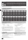
Liquid
side
P200, P250, EP200
Expand the liquid side on-site piping (ID
ø
9.52)
and connect to the refrigerant service valve piping.
P300
Use the included connecting pipe 4 to connect.
P300
*2 *3
Expand the liquid side on-site piping (ID
ø
12.7)
and connect to the refrigerant service valve piping.
EP250, EP300
Use the included connecting pipe 5 to connect.
EP250*1, EP300*2 *3,
P350, P400
Use the included connecting pipe 7 to connect.
P400*3, P450
Expand the liquid side on-site piping (ID
ø
15.88)
and connect to the refrigerant service valve piping.
Gas
side
P200
Expand the gas side on-site piping (ID
ø
19.05)
and connect to the refrigerant service valve piping.
EP200
Use the included connecting pipe 9 to connect.
P250, EP250, P300
Use the included connecting pipe 0 to connect.
EP300
Use the included connecting pipe a to connect.
P350, P400
Use the included connecting pipe b to connect.
P450
Expand the gas side on-site piping (ID
ø
28.58)
and connect to the refrigerant service valve piping.
WT05962X01_GB.indd 17 2010/08/26 19:20:59