


14
GB
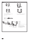
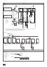
6. Space required around unit
1 In case of single installation
Secure enough space around the unit as shown in the gure on page 2.•
[Fig. 6.0.1] (P.2)
<A> Top view <B> Side view
<C> When there is little space up to an obstruction
A
Front
B
Unit height
C
Back
D
Air outlet guide (Procured at the site)
(1) If the distance is 300 mm or more between the rear side and the wall
(2) If the distance is 100 mm or more between the rear side and the wall
(3) If the wall height (H) of the front, rear or side exceeds the wall height
restriction
When the height of the walls on the front, back or on the sides <H> exceeds •
the wall height limit as dened here, add the height that exceeds the height
limit <h> to the gures that are marked with an asterisk.
If the unit cannot be kept clear of the wall, please change the direction of the •
air outlet of the unit to blow against the wall to avoid air short cycle.
<Wall height limit> Front: Up to the unit height
Back: Up to 500 mm from the unit bottom
Side: Up to the unit height
(4) If there are obstacles at the upper part of the unit
2 In case of collective installation
[Fig. 6.0.2] (P.2)
A
Front
B
Must be open
C
Wall height (H)
When multiple units are installed adjacent to each other, secure enough •
space to allow for air circulation and walkway between groups of units as
shown in the gures on page 2.
At least two sides must be left open.•
As with the single installation, add the height that exceeds the height limit •
<h> to the gures that are marked with an asterisk.
If there is a wall at both the front and the rear of the unit. Install up to six •
units (three units: P450, EP300) consecutively in the side direction and
provide a space of 1000 mm or more as inlet space/passage space for each
six units (three units: P450, EP300).
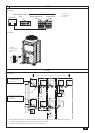
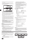
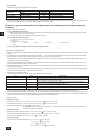
[Fig. 7.0.1] (P.3)
Use suspension ropes that will withstand the weight of the unit.•
When moving the unit, use a • 4-point suspension, and avoid giving impacts
to the unit (Do not use 2-point suspension).
Place protective pads on the unit where it comes in contact with the ropes to •
protect the unit from being scratched.
Set the angle of roping at 40° or less.•
Use 2 ropes that are each longer than 8 meters.•
Place protective padding at the corners of the product to protect the product •
from scratches or dents that might be caused by the rope.
Caution:
Be very careful when carrying/moving the product.
- When installing the outdoor unit, suspend the unit at the specied location of
the unit base. Stabilize as necessary so that it does not move to the side and
support it at 4 points. If the unit is installed or suspended with 3-point support,
the unit may become unstable and fall.
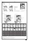
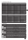
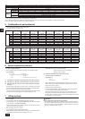
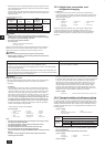
7. Lifting method
Model
PUHY-EP650YSJM-A PUHY-EP700YSJM-A
PUHY-EP700YSJM-A1
PUHY-EP750YSJM-A
PUHY-EP750YSJM-A1
PUHY-EP800YSJM-A
PUHY-EP800YSJM-A1
PUHY-EP850YSJM-A PUHY-EP900YSJM-A
Noise level (50/60Hz)
63dB<A> 63.5dB<A> 64dB<A> 64.5dB<A> 65dB<A> 65dB<A> 65dB<A> 65.5dB<A> 66dB<A>
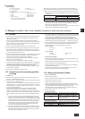
External static pressure 0 Pa *2
Indoor units
Total capacity
50~130% *1
Model
15~250
Quantity 1~50 1~50 1~50 1~50 1~50 1~50 1~50 1~50 1~50
Operation
temperature
Standard type
Cooling mode: – 5°CDB ~ 46°CDB
Heating mode: – 20°CWB ~ 15.5°CWB
Fresh air
intake type
Cooling mode: 21°CDB ~ 43°CDB
Heating mode: – 12.5°CWB ~ 20°CWB
*1: The total indoor capacity of units run simultaneously is 130% or less.
*2: To enable high static pressure with (E)P200, (E)P250, (E)P300, P350, P400, and P450, set the DipSW on the main panel as follows.
SW3-9: ON, SW3-10 60Pa compatible: OFF, 30Pa compatible: ON
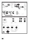
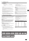
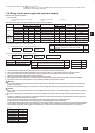
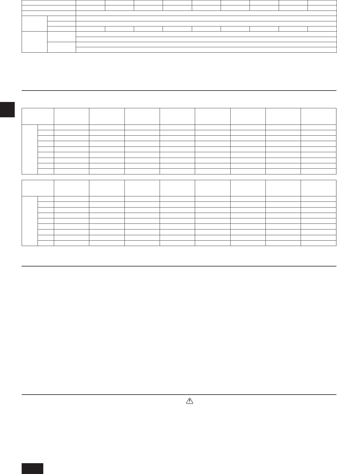
5. Conrmation of parts attached
This unit includes the following parts. Please check.•
For usage methods, refer to item 10.2.•
1 Connecting elbow
ID
ø
19.05, OD
ø
19.05
<Gas side>
2 Connecting elbow
ID
ø
25.4, OD
ø
25.4
<Gas side>
3 Connecting elbow
ID
ø
28.58, OD
ø
28.58
<Gas side>
4 Connecting pipe
ID
ø
12.7, OD
ø
9.52
<Liquid side>
5 Connecting pipe
ID
ø
15.88, OD
ø
9.52
<Liquid side>
6 Connecting pipe
ID
ø
9.52, OD
ø
12.7
<Liquid side>
7 Connecting pipe
ID
ø
15.88, OD
ø
12.7
<Liquid side>
8 Connecting pipe
ID
ø
15.88, OD
ø
19.05
<Liquid side>
Model P200 1pc. - - - - - - -
P250 - 1pc. - - - - - -
P300 - 1pc. - 1pc. - - - -
P350 - 1pc. - - - - 1pc. -
P400 - 1pc. - - - - 1pc. -
P450 - - 1pc. - - - - -
EP200 - 1pc. - - - - - -
EP250 - 1pc. - - 1pc. 1pc. 1pc. 1pc.
EP300 - - 1pc. - 1pc. - 1pc. -
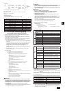
9 Connecting pipe
ID
ø
25.4, OD
ø
19.05
<Gas side>
0 Connecting pipe
ID
ø
25.4, OD
ø
22.2
<Gas side>
a Connecting pipe
ID
ø
28.58, OD
ø
22.2
<Gas side>
b Connecting pipe
ID
ø
25.4, OD
ø
28.58
<Gas side>
c Connecting pipe
ID
ø
28.58, OD
ø
34.93
<Gas side>
d Connecting pipe
ID
ø
9.52, OD
ø
9.52
<Liquid side>
e Connecting pipe
ID
ø
12.7, OD
ø
12.7
<Liquid side>
f Connecting pipe
ID
ø
15.88, OD
ø
15.88
<Liquid side>
Model P200 - - - - - 1pc. - -
P250 - 1pc. - - - 1pc. - -
P300 - 1pc. - - - - 1pc. -
P350 - - - 1pc. - - - 1pc.
P400 - - - 1pc. - - - 1pc.
P450 - - - - - - - 1pc.
EP200 1pc. - - - - 1pc. - -
EP250 - 1pc. - - 1pc. - - 1pc.
EP300 - - 1pc. - - - - 1pc.
WT05962X01_GB.indd 14 2010/08/26 19:20:57