


15
GB
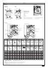
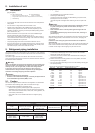
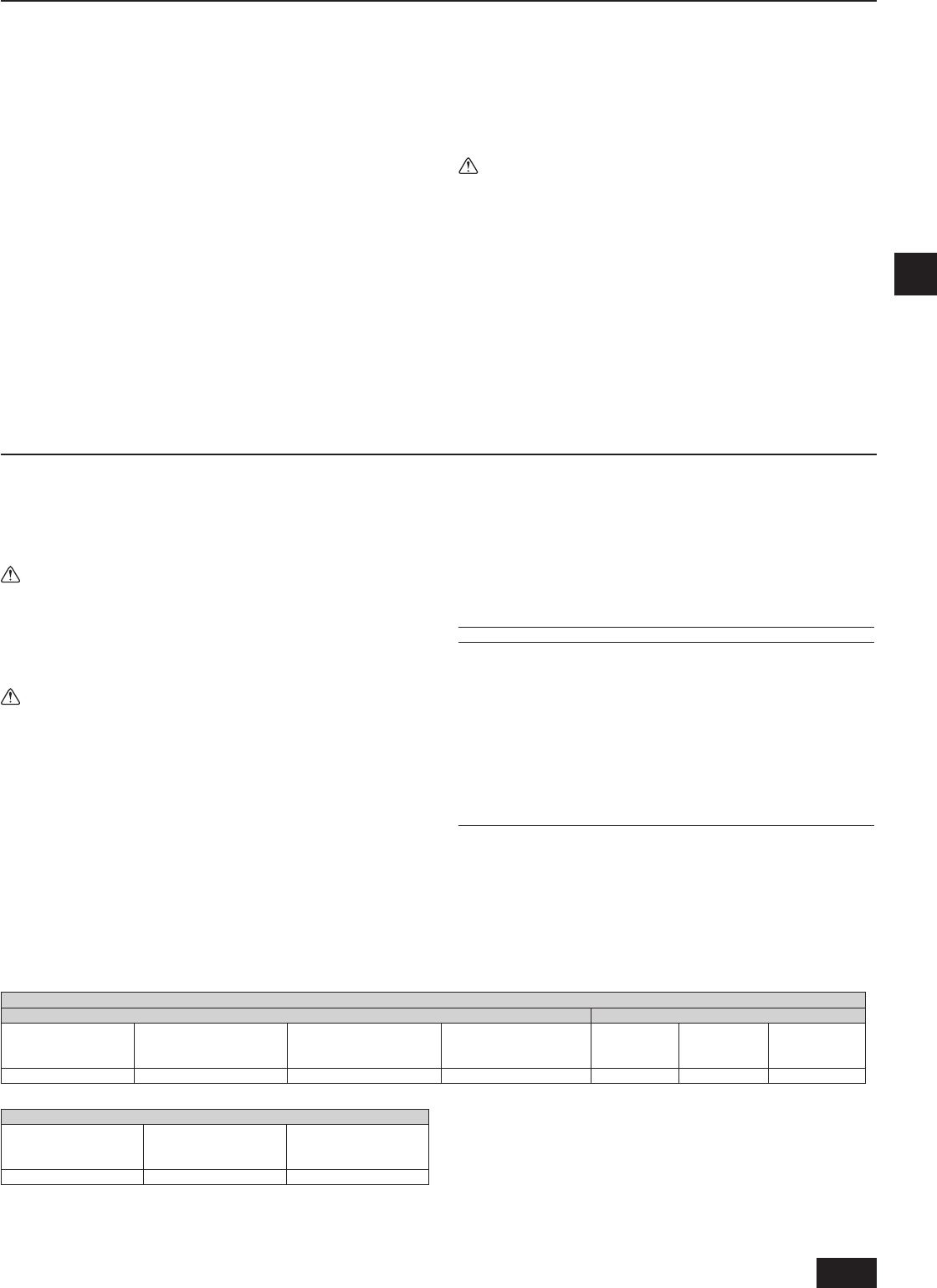
8.1. Installation
[Fig. 8.1.1] (P.3)
<A> Without detachable leg <B> With detachable leg
A
M10 anchor bolt procured at the site.
B
Corner is not seated.
C
Fixing bracket for the hole-in anchor bolt (3 locations to x with screws).
D
Detachable leg
Fix unit tightly with bolts so that unit will not fall down due to earthquakes or •
strong winds.
Use concrete or an angle bracket as the foundation of unit.•
Vibration may be transmitted to the installation section and noise and •
vibration may be generated from the oor and walls, depending on the
installation conditions. Therefore, provide ample vibrationproong (cushion
pads, cushion frame, etc.).
Build the foundation in such way that the corner of the installation leg is •
securely supported as shown in the gure. (Fig. 8.1.1)
When using a rubber isolating cushion, please ensure it is large enough to
cover the entire width of each of the unit's legs. If the corners are not rmly
seated, the installation feet may be bent.
The projecting length of the anchor bolt should be less than 30 mm.•
Hole-in anchor bolts are not compatible with this product. However, if xing •
brackets are mounted on the 4 locations (6 locations: P450, EP300) of the
unit attachment part, hole-in anchor bolts can be used.
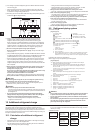
[Fig. 8.1.2] (P.3)
A
Screws
The detachable leg can be removed at the site.•
Detaching the detachable leg•
Loosen the three screws to detach the detachable leg (Two (three: P450,
EP300) each in the front and back).
If the base leg nish is damaged when detaching, be sure to repair at the
site.
Warning:
Be sure to install unit in a place strong enough to withstand its weight.•
Any lack of strength may cause unit to fall down, resulting in a
personal injury.
Have installation work in order to protect against strong winds and •
earthquakes.
Any installation deciency may cause unit to fall down, resulting in a
personal injury.
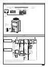
When building the foundation, give full attention to the oor strength, drain water
disposal <during operation, drain water ows out of the unit>, and piping and
wiring routes.
Precautions when routing the pipes and wires below the unit (Without
detachable leg)
When routing the pipes and wires below the unit, be sure that the foundation and
base work do not block the base through-holes. Also make sure the foundation
is at least 100 mm high so that the piping can pass under the unit.
8. Installation of unit
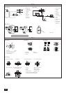
9. Refrigerant piping installation
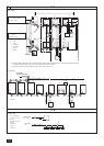
The pipe is connected via a terminal-branch type connection in which refrigerant
piping from the outdoor unit is branched at the terminal and is connected to each
of the indoor units.
The method of pipe connection is as follows: are connection for the indoor
units, gas pipes and liquid pipes for outdoor units, brazed connection. Note that
the branched sections are brazed.
Warning:
Always use extreme care to prevent the refrigerant gas from leaking while
using re or ame. If the refrigerant gas comes in to contact with a ame
from any source, such as a gas stove, it breaks down and generates
a poisonous gas which can cause gas poisoning. Never weld in an
unventilated room. Always conduct an inspection for gas leakage after
installation of the refrigerant piping has been completed.
Caution:
Do not vent R410A into the atmosphere.•
R410A is a Fluorinated Greenhouse gas, covered by the Kyoto Protocol •
with a Global Warming Potential (GWP) = 1975.
9.1. Caution
This unit uses refrigerant R410A. Follow the local regulations on materials and
pipe thickness when selecting pipes. (Refer to the table on the right.)
1 Use the following materials for refrigeration piping.
Material: Use copper alloy seamless pipes made of phosphorus •
deoxidized copper. Ensure the inner and outer surfaces of the pipes are
clean and free from hazardous sulfur, oxide, dusts, shaving particles, oils,
and moisture (contamination).
Size: Refer to item 9.2. for detailed information on refrigerant piping •
system.
2 Commercially available piping often contains dust and other materials.
Always blow it clean with a dry inert gas.
3 Use care to prevent dust, water or other contaminants from entering the
piping during installation.
4 Reduce the number of bending portions as much as possible, and make
bending radii as big as possible.
5 For indoor and outdoor branching, be sure to use the following twinning pipe
sets (sold separately).
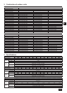
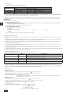
Copper pipe size and radial thickness for R410A CITY MULTI.
Size (mm) Size (inch) Radial thickness (mm) Pipe type
ø6.35 ø1/4" 0.8 Type-O
ø9.52 ø3/8" 0.8 Type-O
ø12.7 ø1/2" 0.8 Type-O
ø15.88 ø5/8" 1.0 Type-O
ø19.05 ø3/4" 1.2 Type-O
ø19.05 ø3/4" 1.0 Type-1/2H or H
ø22.2 ø7/8" 1.0 Type-1/2H or H
ø25.4 ø1" 1.0 Type-1/2H or H
ø28.58 ø1-1/8" 1.0 Type-1/2H or H
ø31.75 ø1-1/4" 1.1 Type-1/2H or H
ø34.93 ø1-3/8" 1.2 Type-1/2H or H
ø41.28 ø1-5/8" 1.4 Type-1/2H or H
* For pipe sized ø19.05 (3/4") for R410A air conditioner, choice of pipe type is
up to you.
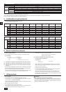
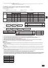
Indoor twinning pipe set model
Line branch Header branch
Lower stream unit
model
Less than 200 in total
Lower stream unit model
More than 201 and less
than 400 in total
Lower stream unit model
More than 401 and less
than 650 in total
Lower stream unit model
More than 651 in total
4 branching 8 branching 10 branching
CMY-Y102S-G2 CMY-Y102L-G2 CMY-Y202-G2 CMY-Y302-G2 CMY-Y104-G CMY-Y108-G CMY-Y1010-G
Outdoor twinning kit model
Total outdoor model
P500 ~ P650
EP400 ~ EP600
Total outdoor model
P700 ~ P900
Total outdoor model
P950 ~ P1250
EP650 ~ EP900
CMY-Y100VBK2 CMY-Y200VBK2 CMY-Y300VBK2
WT05962X01_GB.indd 15 2010/08/26 19:20:57