


10
A B C
E
D
M1M2
M1M2
M1M2
S
TB7
TB3
IC
(51)
M1 M2 12S
TB5TB15
12
TB15
12
TB15
12
TB15
12
TB15
12
TB15
MA
(01)
IC
M1 M2 S
TB5
(02)
IC
M1 M2 S
TB5
(04)
IC
M1 M2 S
TB5
(03)
IC
M1 M2 S
TB5
(05)
IC
M1 M2 S
TB5
(07)
IC
M1 M2 S
TB5
(06)
L
2
L
1
MA
MA
MA
OC
M1M2
S
TB7
TB3
(52)
OC
m
1
m
1
m
1
m
4
m
3
S
System
controller
L
3
L
6
L
4
AB
AB
AB
AB
AB
m
2
m
2
m
2
CN40
CN40
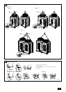
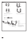
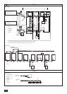
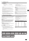
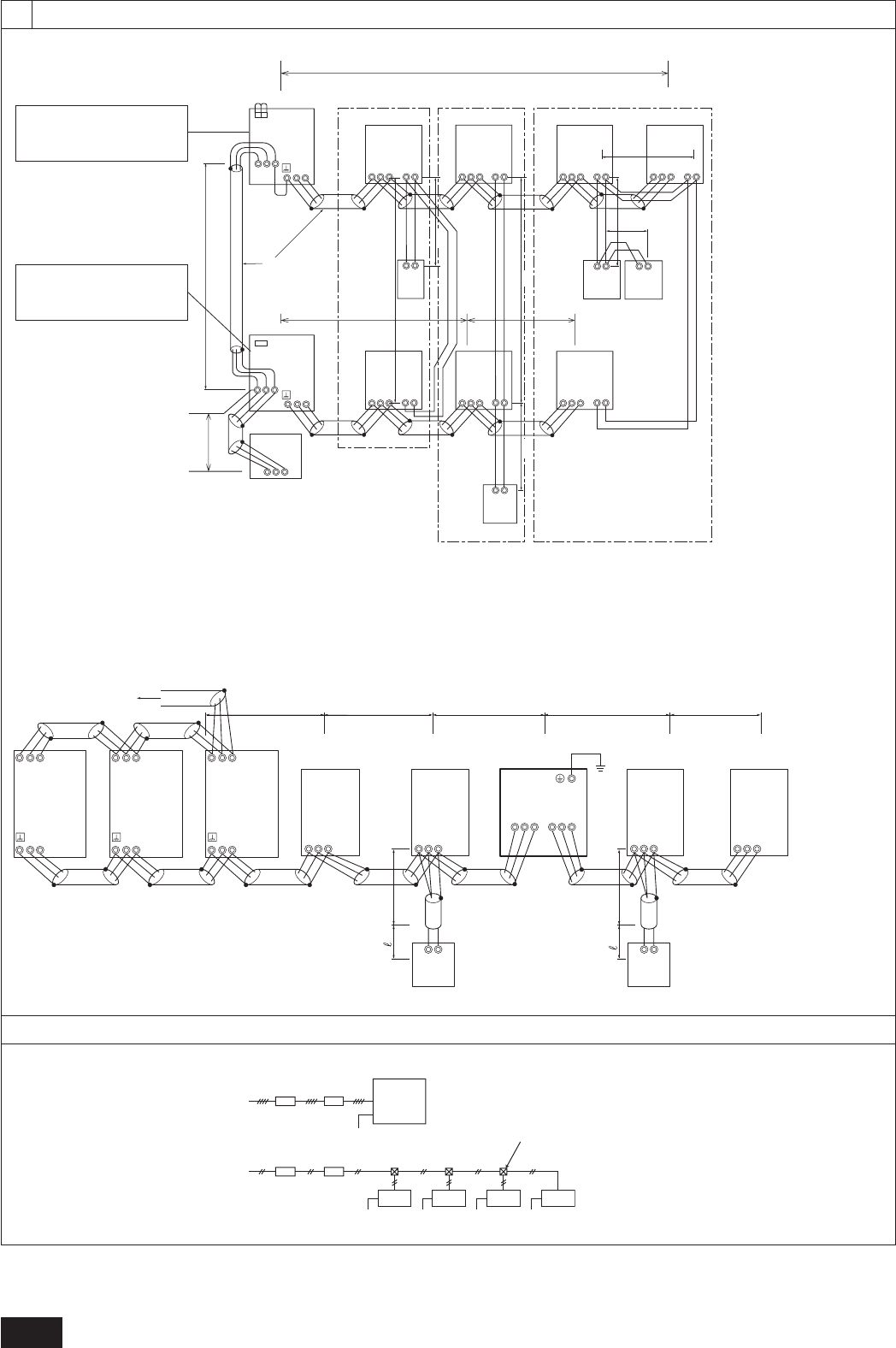
[Fig. 11.3.2]
A : Group 1
B : Group 3
C : Group 5
D : Shielded wire
E : Sub remote
controller
( ) Address
<A> Change the jumper connector
from CN41 to CN40 *1
<B> SW2-1:ON *2
<C> Keep the jumper connector
on CN41
<B> SW2-1:ON *2
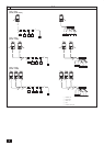
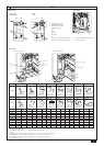
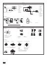
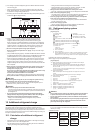
[Fig. 11.3.3]
RC
IC
M1M2 S
TB5
IC
M1M2 S
TB5
RP
Ground
AB
ABAB
S
TB2
ABS
TB3
L
4
1
1
M1M2
TB3
M1M2
TB3
M1M2
M1M2 S
TB3
TB7
M1M2 S
TB7
M1M2 S
TB7
OC
(51)
L
7
RC
IC
M1M2 S
TB5
IC
M1M2 S
TB5
L
6
L
5
L
3
L
2
L
1
OS1
(52)
OS2
(53)
To another
refrigerant system
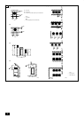
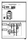
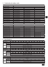
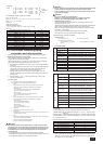
[Fig. 11.4.1]
A : Switch (Breakers for
wiring and current
leakage)
B : Breakers for current
leakage
C : Outdoor unit
D : Pull box
E : Indoor unit
BA
C
3N~380–415V
L
1
, L
2
, L
3,
N
BA
~220–240V
L, N
Earth
Earth Earth
E
Earth Earth
E
D
E E
( ) Address
11.4
11.3
11
*1: When the power supply unit is not connected to the transmission line for centralized control, disconnect the male power supply
connector (CN41) from ONE outdoor unit in the system and connect it to CN40.
*2: If a system controller is used, set SW2-1 on all of the outdoor units to ON.