


90
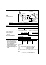
4-way valve coil
(21S4)
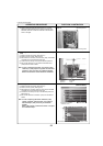
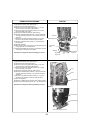
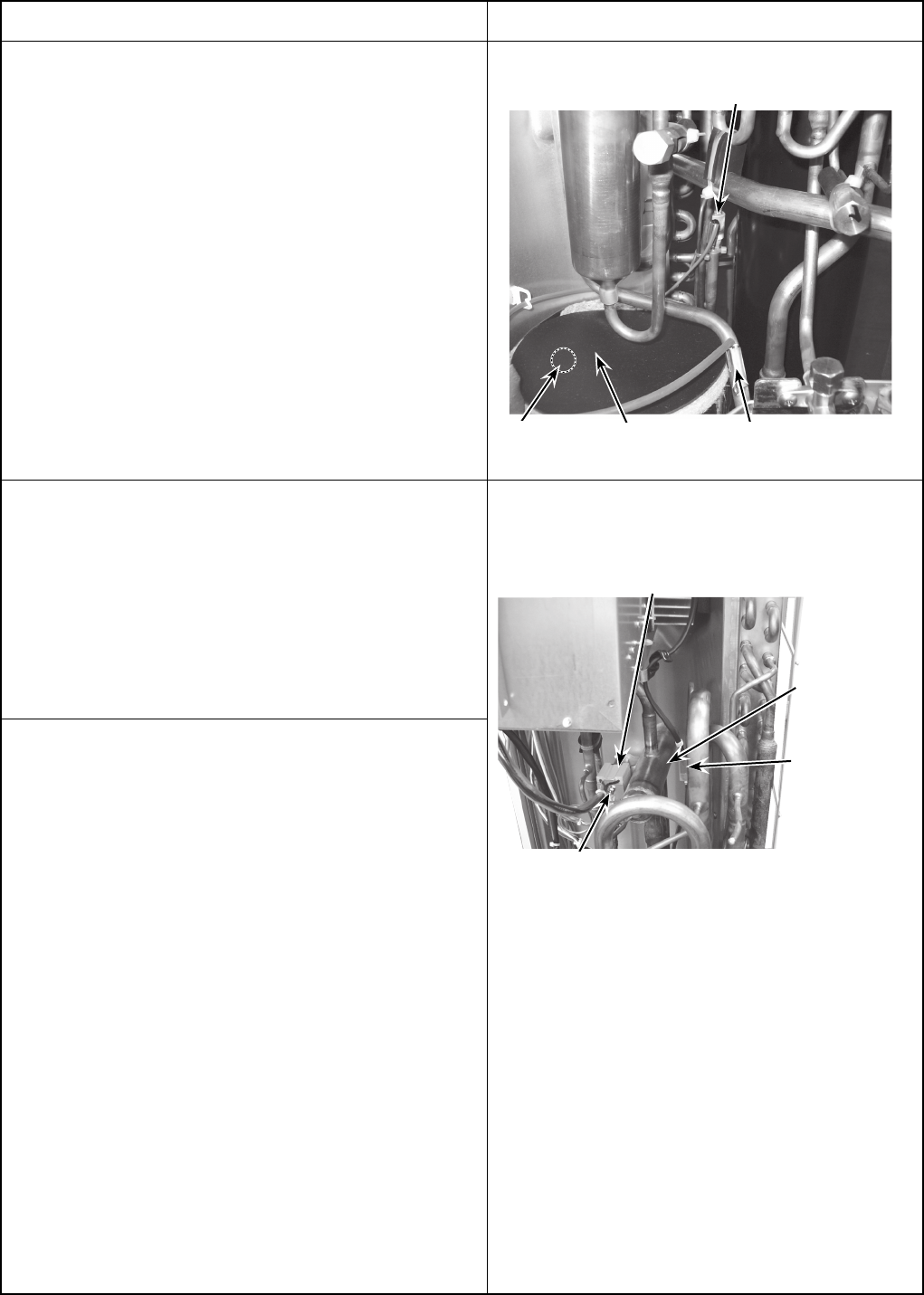
7. Removing the 4-way valve coil (21S4)
(1) Remove the service panel. (See Figure 1)
(2) Remove the top panel. (See Figure 1)
[Removing the 4-way valve coil]
(3) Remove 4-way valve solenoid coil fixing screw (M4 × 6).
(4)
Remove the 4-way valve coil by sliding the coil toward you.
(5) Disconnect the connector 21S4 (green) on the Multi con-
troller board in the electrical parts box.
Photo 8
4-way
valve
Thermistor
<Low pressure
saturated temp.>
(TH6)
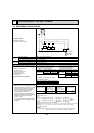
OPERATING PROCEDURE
PHOTOS
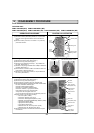
Photo 7
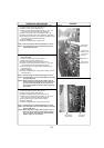
6. Removing the thermistor <Outdoor pipe> (TH3) and ther-
mistor <Discharge/Compressor> (TH4)
(1) Remove the service panel. (See Figure 1)
(2) Disconnect the connectors, TH3 (white) and TH4 (white),
on the Multi controller board in the electrical parts box.
(3) Loosen the clamp for the lead wire in the rear of the elec-
trical parts box.
(4) Pull out the thermistor <Outdoor pipe> (TH3) and ther-
mistor <Discharge/Compressor> (TH4) from the sensor
holder.
Thermistor
<Discharge>
(TH4)
Thermistor
<Outdoor pipe>
(TH3)
Compressor
(MC)
4-way valve coil
fixing screw
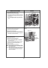
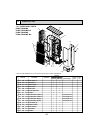
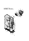
8. Removing the 4-way valve
(1) Remove the service panel. (See Figure 1)
(2) Remove the top panel. (See Figure 1)
(3) Remove 3 valve bed fixing screws (4 × 10) and 4 ball
valve and stop valve fixing screws (5 × 16) and then
remove the valve bed.
(4) Remove 5 right side panel fixing screws (5 × 12) in the
rear of the unit and then remove the right side panel.
(5) Remove the 4-way valve coil. (See Photo 8)
(6) Recover refrigerant.
(7) Remove the welded part of 4-way valve.
Note 1: Recover refrigerant without spreading it in the air.
Note 2: The welded part can be removed easily by remov-
ing the right side panel.
Note 3: When installing the 4-way valve, cover it with a wet
cloth to prevent it from heating (120 °C [248 °F] or
more), then braze the pipes so that the inside of
pipes are not oxidized.
Thermistor
<Compressor>
(TH4)