


5
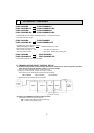
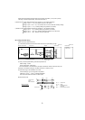
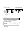
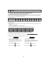
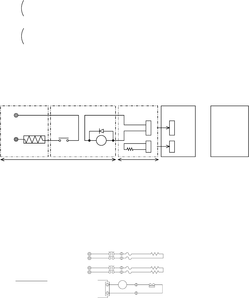
(6) Locally procured wiring
A basic connection method is shown.
(i.e. interlocked operation with the electric heater with the fan speed setting on high
Recommended circuit
CN24
CN22
X
+
X
Remote control Board Relay circuit
Adapter
Indoor unit
control board
Outdoor unit
control board
Electr
ic Heater
power source
Electric
Heater
Red 1
White 2
Dip switch
SW4-4 "ON"
Preparations in the field
Maximum cable length
is 10 m (32ft)
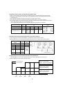
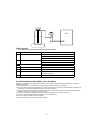
Red 1
Red 2
Yello
w
Green
FS1
FS2
FS1
FS2
R
S
R
S
CN24
H2
88H
H1
88H
26H
88H
1-phase power
supply
208V, 230V/60Hz
Control board
FS1, 2 ----- Thermal fuse
H1, H2 ----- Heater
26H--------- Overheat protection
thermostat
88H--------- Electromagnetic contactor
Wiring diagram
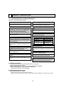
For relay X use the specifications given below Operation coil
Rated voltage : 12VDC
Power consumption : 0.9W or less
*Use the diode that is recommended by the relay manufacturer at both ends of the relay coil.
The length of the electrical wiring for the PAC-YU24HT is 2 meters (6-1/2 ft)
To extend this length, use sheathed 2-core cable.
Control cable type : CVV, CVS, CPEV or equivalent.
Cable size : 0.5 mm
2
~ 1.25 mm
2
(AWG22 to AWG16)
Don`t extend the cable more than 10 meters (32ft).
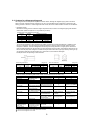
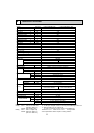
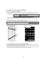
When the set temperature ranges overlap, the previously set pattern (1,2 or 3) has a priority.
The stage 1 has the highest priority, 2 the second and then 3.
b) Based on above chart listed the sequence of operation on "On Ambient Decrease"
Stage 1 :(TH7 = > 10
:
) : the Outdoor unit runs in HP mode.
Stage 2 :(TH7 = 10
:
to -12
:
) : the Outdoor unit runs in HP mode with Auxiliary heating.
Stage 3 :(TH7 = < -12
:
) : Auxiliary heating only (Outdoor unit is OFF).
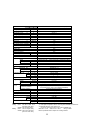
c) Based on above chart listed the sequence of operation on " On Ambient Increase"
Stage 3 :(TH7 = < 0
:
) : Auxiliary heating only (Outdoor unit is OFF).
Stage 2 :(TH7 = > 0
:
to 20
:
) : Auxiliary heating with Outdoor unit in HP mode.
Stage 1 :(TH7 = > 20
:
) : Outdoor unit in HP mode only.