


79
175
176
177
178
179
180
181
182
183
184
185
186
187
188
189
192
193
195
196
197
198
199
200
201
202
203
204
206
207
208
209
210
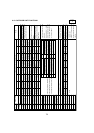
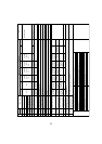
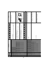
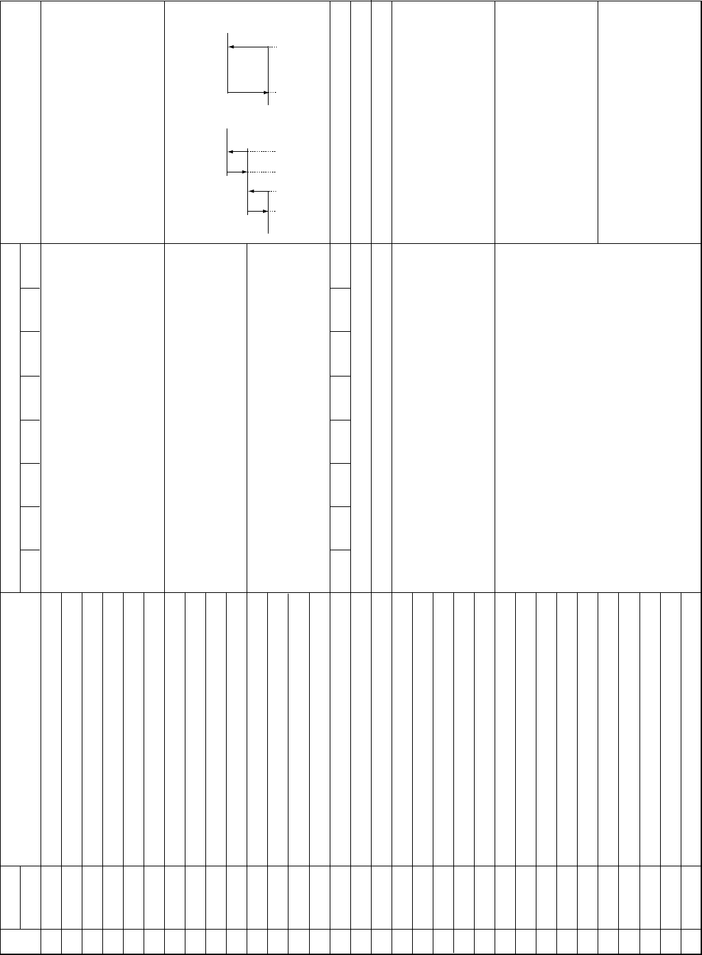
SW1 setting
12345678
11110101
00001101
10001101
01001101
11001101
00101101
10101101
01101101
11101101
00011101
10011101
01011101
11011101
00111101
10111101
00000011
10000011
11000011
00100011
10100011
01100011
11100011
00010011
10010011
01010011
11010011
00110011
01110011
11110011
00001011
10001011
01001011
IC3 TH22 Liquid °F
IC4 TH22 Liquid °F
IC5 TH22 Liquid °F
IC6 TH22 Liquid °F
IC7 TH22 Liquid °F
IC8 TH22 Liquid °F
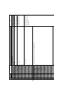
Primary heating control setting temp. a
Primary heating control setting temp. b
Primary heating control setting temp. c
Primary heating control setting temp. d
Primary heating control setting temp. a°F
Primary heating control setting temp. b°F
Primary heating control setting temp. c°F
Primary heating control setting temp. d°F
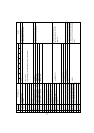
4220 Error history
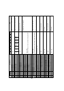
Actual frequency at time of abnormality
Fan step number at time of abnormality
IC1 LEV opening pulse at time of abnormality
IC2 LEV opening pulse at time of abnormality
IC3 LEV opening pulse at time of abnormality
IC4 LEV opening pulse at time of abnormality
IC5 LEV opening pulse at time of abnormality
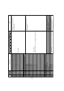
High-pressure sensor data at abnormality kgf/%
TH4 sensor data at time of abnormality °C
TH6 sensor data at time of abnormality °C
TH3 sensor data at time of abnormality °C
TH8 sensor data at time of abnormality °C
IC1 SC/SH at time of abnormality °C
IC2 SC/SH at time of abnormality °C
IC3 SC/SH at time of abnormality °C
IC4 SC/SH at time of abnormality °C
IC5 SC/SH at time of abnormality °C
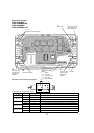
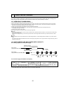
1
2345 6
78
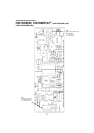
Display on the LED1, 2 (display data)
Display of detection data from each
indoor liquid pipe thermistor
Except Service Ref. PUMY-P48NHMU(-BS)
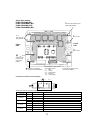
Display of actual frequency at time of abnormality
Display of fan step number at time of abnormality
Display of opening pulse of outdoor SLEV
and indoor LEV at time of abnormality
Display of data from high-pressure sensor
and all thermistors at time of abnormality
Display of data from SC/SH and all
thermistors at time of abnormality
-99.9 ~ 999.9 [°F]
(When the indoor unit is not connected,it is displayed as"32".)
-12a<b<c<d40or
a=c and b=d, -12a<d40
Initial value a= -12, b=0, c=10, d=20
10.4°Fa<b<c<d104°For
a=c and b=d, 10.4°Fa<d104°F
Initial value a=10.4°F, b=32°F, c=50.0°F, d=68.0°F
0~FF(16progressive)
0~20
0~2000
-99.9 ~ 999.9
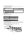
No.
Display mode
Notes
Ex. a=-5, b=5, c=15, d=25
SET :
05 18 00 80 05 00 05 00 15 00 25
MONI : 25 18 00
Primary heating control: SW4-4 ON
HD=05, CM=18 op1=00()/01(°F)
op2,op3=a op4,op5=b op6, op7=c op8,op9=d
ab cd
a=c b=d
—
—
ACTM
error
——
CT sensor
disconnection
Under
voltage
Over
voltage