


76
64
65
66
67
69
70
71
72
73
74
75
76
77
78
80
81
82
83
84
85
86
87
88
89
90
91
92
93
94
95
96
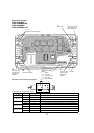
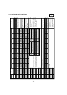
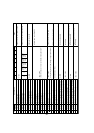
SW1 setting
12345678
00000010
10000010
01000010
11000010
10100010
01100010
11100010
00010010
10010010
01010010
11010010
00110010
10110010
01110010
00001010
10001010
01001010
11001010
00101010
10101010
01101010
11101010
00011010
10011010
01011010
11011010
00111010
10111010
01111010
11111010
00000110
Operational frequency
Target frequency
Outdoor fan control step number
EER fan control step number (cooling)
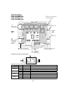
IC1 LEV Opening pulse
IC2 LEV Opening pulse
IC3 LEV Opening pulse
IC4 LEV Opening pulse
IC5 LEV Opening pulse
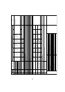
High-pressure sensor (Pd) kgf/cm
2
TH4(Td) °C
TH6(ET) °C
TH7(Outdoor-temp.) °C
TH3(Outdoor pipe) °C
TH8(Power module) °C
IC1 TH23(Gas) °C
IC2 TH23(Gas) °C
IC3 TH23(Gas) °C
IC4 TH23(Gas) °C
IC5 TH23(Gas) °C
IC1 TH22(Liquid) °C
IC2 TH22(Liquid) °C
IC3 TH22(Liquid) °C
IC4 TH22 (Liquid) °C
IC5 TH22 (Liquid) °C
IC1 TH21(Intake) °C
IC2 TH21 (Intake) °C
IC3 TH21 (Intake) °C
IC4 TH21 (Intake) °C
IC5 TH21 (Intake) °C
Outdoor SC (cooling) °C
1
2
3
4
7
5
6
8
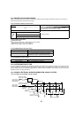
Display of actual operating frequency
Display of target frequency
Display of number of outdoor
fan control steps (target)
Display of opening pulse of
outdoor SLEV and indoor LEV
Display of outdoor subcool
(SC) data and detection data
from high-pressure sensor and
each thermistor
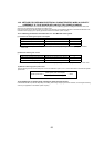
Notes
0~FF(16 progressive)
0~255
0~15
0~2000
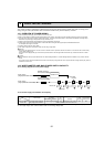
Display mode
Display on the LED1, 2 (display data)
-99.9 ~ 999.9
-99.9 ~ 999.9
-99.9 ~ 999.9
(When the indoor unit is not connected,it is displayed as"0".)
No.