


72
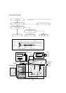
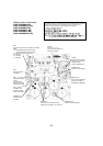
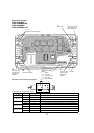
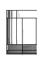
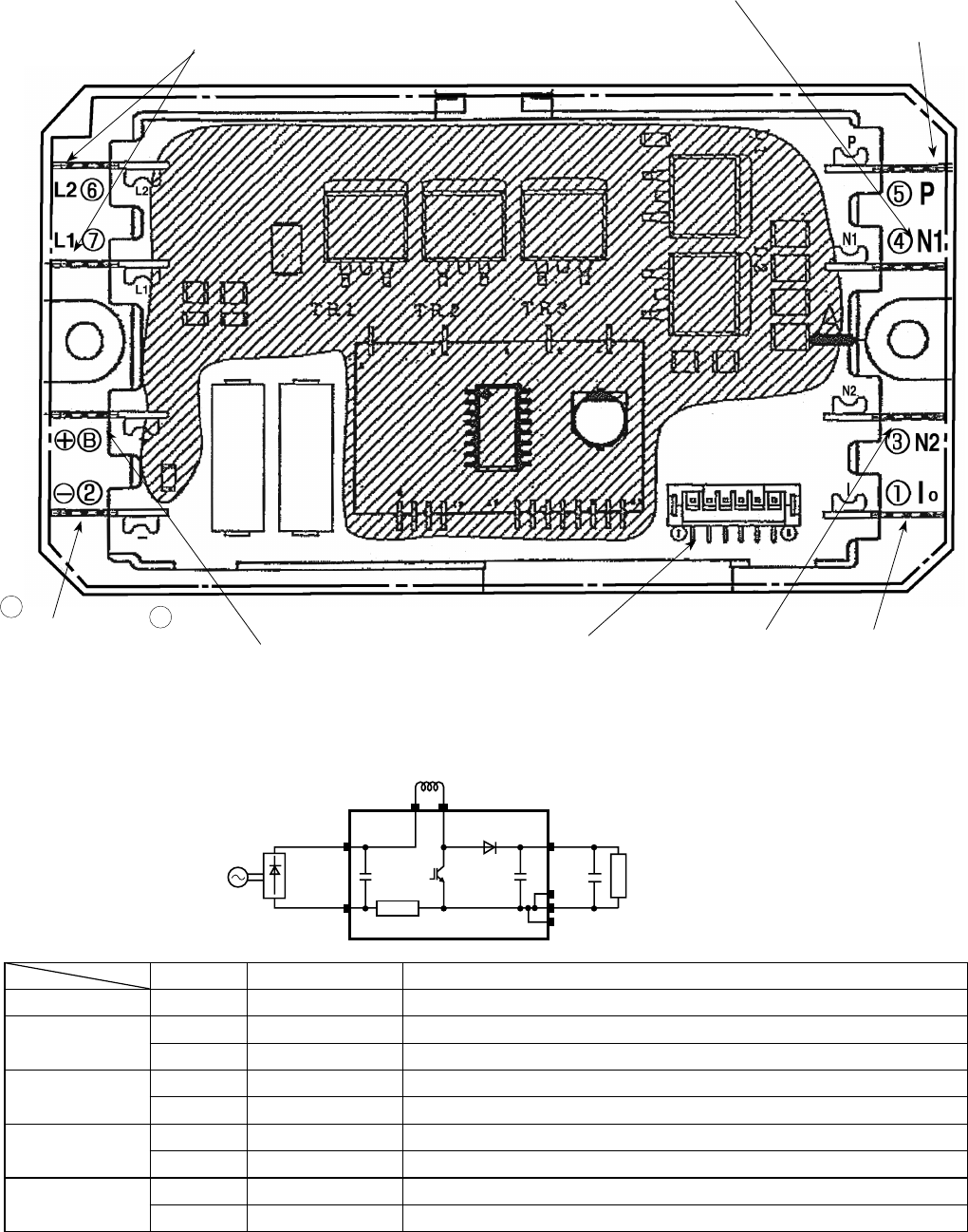
Active filter module
PUMY-P48NHMU
PUMY-P48NHMU-BS
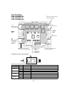
PUMY-P48NHMU
1
PUMY-P48NHMU1-BS
DCL
L1 L2
ACTM
P
I
N1
N2
(+)
(-)
Load
+
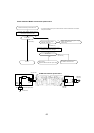
Connection and internal circuit diagram
L1, L2
Connect to the DCL(Reactor)
Connect to the 52C
Connect to the
outdoor power
circuit board
(TABN1)
+
–
I
Not used
N2
Connect to the
outdoor power
circuit board
(TABN2)
N1
Non-connect
P
Connect to the out-
door power circuit
board (TABP2)
Connect to the outdoor
power circuit board
(CNAF)
1 : GND
2-1 : 15V DC
3-1 : Control signal
4, 5 : Not used
6-1 : Control signal
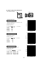
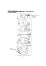
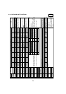
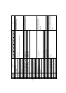
Error condition Normal value (reference)
Symptom when the unit is in trouble
(–) and N1 / N2 / I open less than 1
"
1
The unit does not operate (can not be switched ON)
(–) and L2
short 100k
"
~ 1M
"
1
The breaker operates
open
W
1
The unit does not operate (can not be switched ON)
2
4220 Abnormal stop (9-10. No.189 "ACTM error" display)
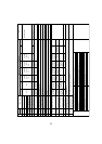
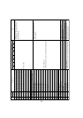
P and L2
short 100k
"
~ 1M
"
1
The breaker operates
open
W
1
The unit does not operate (can not be switched ON)
2
4220 Abnormal stop (9-10. No.189 "ACTM error" display)
P and N1 / N2 / I
short 100k
"
~ 1M
"
1
The breaker operates
open
W
1
The unit does not operate (can not be switched ON)
2
4220 Abnormal stop (9-10. No.189 "ACTM error" display)
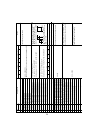
L2 and N1 / N2 / I
short 100k
"
~ 1M
"
1
The breaker operates
open
W
1
The unit does not operate (can not be switched ON)
2
4220 Abnormal stop (9-10. No.189 "ACTM error" display)
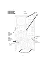
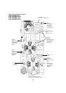
Tester check points of Active fi lter module
W
The symptom when the unit is in open error condition is described to determine open error by tester check.