


25
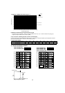
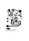
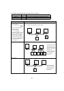
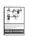
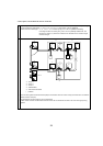
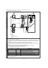
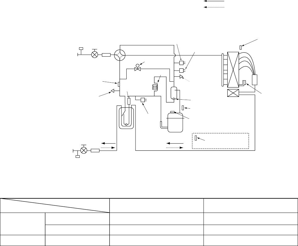
8-2. REFRIGERANT SYSTEM DIAGRAM
PUMY-P36NHMU(-BS) PUMY-P36NHMUR1(-BS)
PUMY-P48NHMU(-BS) PUMY-P48NHMU
1(-BS) PUMY-P48NHMU2(-BS)
PUMY-P48NHMUR3(-BS)
Refrigerant Gas pipe
<5/8 inch>
Refrigerant Liquid pipe
<3/8 inch>
Check valve<Low pressure>
Accumulator
Thermistor<Saturation temperature
of suction pressure>(TH6)
Solenoid
valve(SV1)
Capillary tube
Check valve
<High pressure>
Pressure sensor
(63HS)
High pressure
switch(63H)
Low pressure
switch(63L)
Thermistor(TH7)
(Outdoor temperature)
Discharge
thermistor(TH4)
Compressor
thermistor(TH4)
(P36NHMUR1,P48NHMUR3)
Heatsink
thermistor(TH8)
Thermistor(TH3)
(Pipe temperature)
Oil separator
Service port
Service
port
4-way valve
Strainer
Strainer
Strainer
Stop valve
Stop valve
Distributor
Compressor
Strainer
Refrigerant flow in cooling
Refrigerant flow in heating
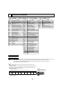
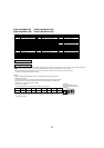
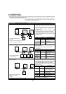
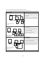
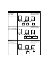
Refrigerant piping specifications <dimensions of flared connector>
Unit:mm<inch>
Capillary tube (for oil separator) : :2.5 % :0.8 % L1000(mm) [:(3/32) % :(1/32) % L(39-1/2)] inch
Capacity
Item
Liquid piping
Gas pipng
P06, P08, P12, P15, P18
P24, P30, P36, P48, P54
P36, P48
Indoor unit
Outdoor unit
:6.35<1/4>
:9.52<3/8>
:9.52<3/8>
:12.7<1/2>
:15.88<5/8>
:15.88<5/8>