


60
Notes
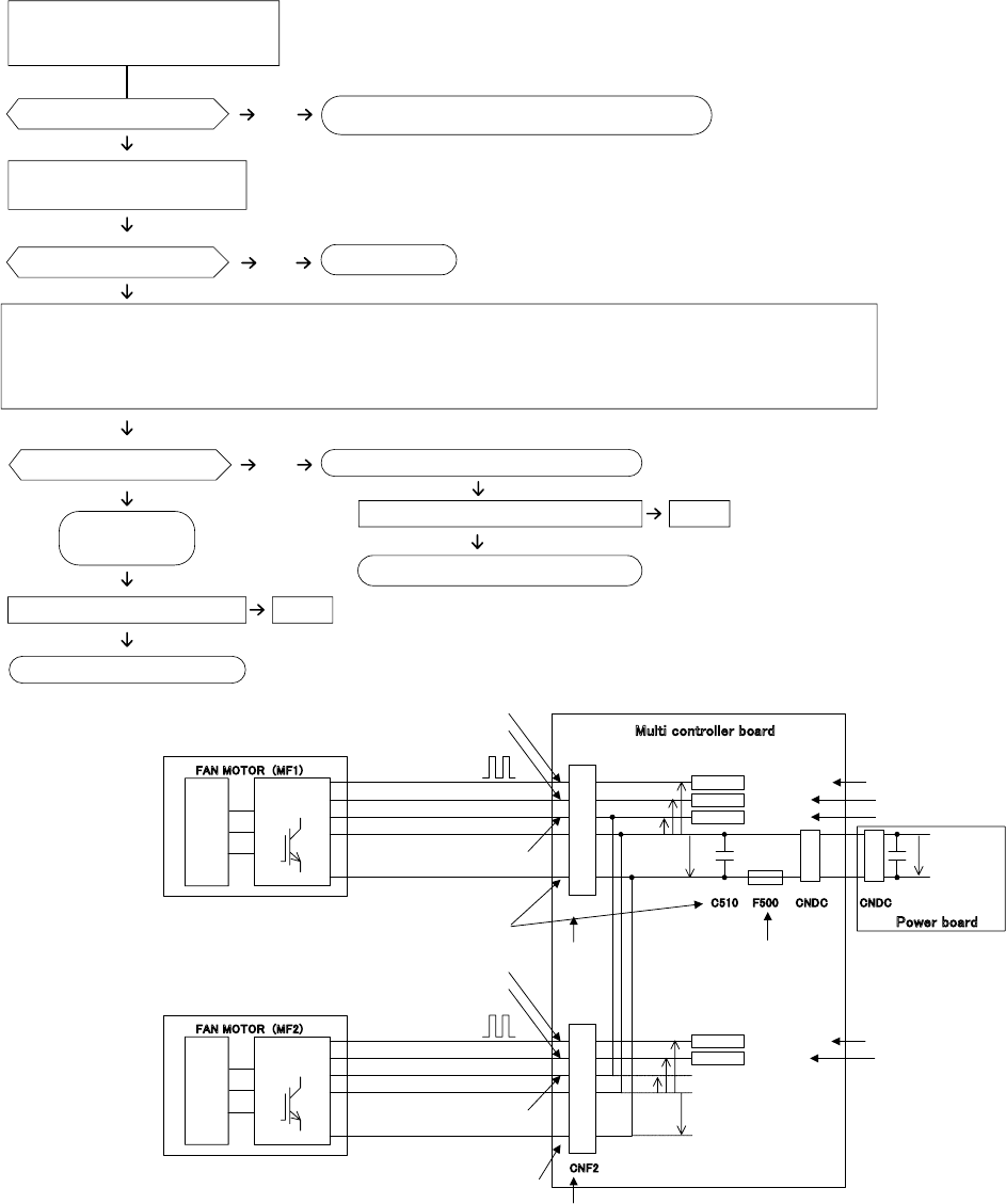
· High voltage is applied to the connecter (CNF1, 2) for the fan motor. Pay attention to the service.
· Do not pull out the connector (CNF1, 2) for the motor with the power supply on.
(It causes trouble of the outdoor controller circuit
board and fan motor.)
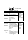
Self check
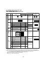
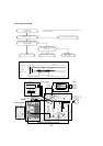
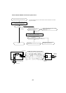
Symptom : The outdoor fan cannot turn around.
Check method of DC fan motor (fan motor / outdoor controller circuit board)
Power supply check(Remove the connector (CNF1, 2))
Measure the voltage in the outdoor controller circuit
board.
TEST POINT
: VDC (between 1 (+) and 4 (-) of the fan connector):
V
DC
DC280-340V (When ACTM stops), DC350V (When ACTM is operating)
TEST POINT : VCC (between 5 (+) and 4 (-) of the fan connector): VCC DC15V
No
NG
NG
Wiring contact check
Contact of fan motor connector (CNF1, 2)
Fuse check
Check the fuse (F500) on outdoor
controller board.
Recover wiring.
Replace outdoor controller board.
Replace the fan motor.
Replace outdoor controller board (MULTI.B.) (C.B)
and fan motor (MF1, 2).
Replace outdoor
controller board.
Replace the fan motor.
Is the voltage normal?
Is there contact failure?
Yes
Yes
No
Did the fuse blow?
No
Yes
Check the operation of fan. END
Yes
OK
Check the operation. END
OK
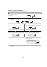
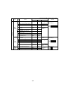
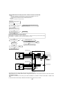
㪝㪘㪥㩷㪤㪦㪫㪦㪩䇭㩿㪤㪝㪈㪀
㪠㫅㫍㪼㫉㫋㪼㫉
㪻㫉㫀㫍㪼㫉
㩷㩷㩷㩷㩷㩷㩷㩷㩷㩷㩷㩷㩷㩷㩷㩷㩷㩷㩷㩷㩷㩷㩷㩷㪞㫉㫆㫌㫅㪻
㩷㩷㩷㩷㩷㩷㩷㩷㩷㩷㩷㩷㩷㩷㪓㪄㩷㫇㫆㫎㪼㫉㩷㫊㫌㫇㫇㫃㫐㩷㩿㫀㫅㫍㪼㫉㫋㪼㫉㩷㪻㫉㫀㫍㪼㪀
㩷㩷㩷㩷㩷㩷㩷㩷㩷㩷㩷㩷㩷㩷㪓㪄㩷㫇㫆㫎㪼㫉㩷㫊㫌㫇㫇㫃㫐㩷㩿㪾㪸㫋㪼㩷㪻㫉㫀㫍㪼㪀
㩷㩷㩷㩷㩷㩷㩷㩷㩷㩷㩷㩷㩷㩷㪄㪕㩷㩷㫉㫆㫋㪸㫋㫀㫆㫅㩷㫊㫀㪾㫅㪸㫃
㩷㩷㩷㩷㩷㩷㩷㩷㩷㩷㩷㩷㩷㩷㪓㪄㩷㪺㫆㫅㫋㫉㫆㫃㩷㫍㫆㫃㫋㪸㪾㪼
㪎
㪍
㪌
㪋
㪄
㪄
㪈
㪊
㪄
㪈
㪚㪥㪝㪈
㪚
㪥㪛㪚㪝㪌㪇㪇
㪛㪚㪈㪌㪭
㪛㪚㪇㪄㪍㪅㪌㪭
㪛㪚㪇㪄㪈㪌㪭㩷㫇㫌㫃㫊㪼
㪚㪌㪈㪇
㪤㫌㫃㫋㫀㩷㪺㫆㫅㫋㫉㫆㫃㫃㪼㫉㩷㪹㫆㪸㫉㪻
㪤㫆㫋㫆㫉
㪫㪜㪪㪫㪪㩷㪧㪦㪠㪥㪫㩷㽲㩷㪭
㪛㪚
㪫㪜㪪㪫㪪㩷㪧㪦㪠㪥㪫㩷㽳㩷㪭㪺㪺
㪚㪟㪜㪚㪢㩷㪧㪦㪠㪥㪫
㪂
㪛㪚㪉㪏㪇㪄㪊㪌㪇㪭
㪫㪜㪪㪫㪪㩷㪧㪦㪠㪥㪫㩷㽴㩷㪭㫊㫇
㪧㪚㪌㪈㪈
㪚㪌㪈㪌
㪫㪜㪪㪫㪪㩷㪧㪦㪠㪥㪫㩷㽵㩷㪭
㪝㪞
㪚㪏㪉㪘
㪫㪜㪪㪫㪪㩷㪧㪦㪠㪥㪫㩷㽴㩷㪭㫊㫇
㪫㪜㪪㪫㪪㩷㪧㪦㪠㪥㪫㩷㽵㩷㪭
㪝㪞
㪫㪜㪪㪫㪪㩷㪧㪦㪠㪥㪫㩷㽳㩷㪭㪺㪺
㪚㪟㪜㪚㪢㩷㪧㪦㪠㪥㪫
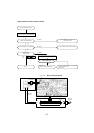
㪝㪘㪥㩷㪤㪦㪫㪦㪩䇭㩿㪤㪝㪉㪀
㪠㫅㫍㪼㫉㫋㪼㫉
㪻㫉㫀㫍㪼㫉
㩷㩷㩷㩷㩷㩷㩷㩷㩷㩷㩷㩷㩷㩷㩷㩷㩷㩷㩷㩷㩷㩷㩷㩷㪞㫉㫆㫌㫅㪻
㩷㩷㩷㩷㩷㩷㩷㩷㩷㩷㩷㩷㩷㩷㪓㪄㩷㫇㫆㫎㪼㫉㩷㫊㫌㫇㫇㫃㫐㩷㩿㫀㫅㫍㪼㫉㫋㪼㫉㩷㪻㫉㫀㫍㪼㪀
㩷㩷㩷㩷㩷㩷㩷㩷㩷㩷㩷㩷㩷㩷㪓㪄㩷㫇㫆㫎㪼㫉㩷㫊㫌㫇㫇㫃㫐㩷㩿㪾㪸㫋㪼㩷㪻㫉㫀㫍㪼㪀
㩷㩷㩷㩷㩷㩷㩷㩷㩷㩷㩷㩷㩷㩷㪄㪕㩷㩷㫉㫆㫋㪸㫋㫀㫆㫅㩷㫊㫀㪾㫅㪸㫃
㩷㩷㩷㩷㩷㩷㩷㩷㩷㩷㩷㩷㩷㩷㪓㪄㩷㪺㫆㫅㫋㫉㫆㫃㩷㫍㫆㫃㫋㪸㪾㪼
㪎
㪍
㪌
㪋
㪄
㪄
㪈
㪚㪥㪝㪉
㪛㪚㪇㪄㪍㪅㪌㪭
㪛㪚㪇㪄㪈㪌㪭㩷㫇㫌㫃㫊㪼
㪤㫆㫋㫆㫉
㪫㪜㪪㪫㪪㩷㪧㪦㪠㪥㪫㩷㽲㩷㪭
㪛㪚
㪫㪜㪪㪫㪪㩷㪧㪦㪠㪥㪫㩷㽴㩷㪭㫊㫇
㪧㪚㪌㪈㪉
㪚㪌㪈㪍
㪫㪜㪪㪫㪪㩷㪧㪦㪠㪥㪫㩷㽵㩷㪭
㪝㪞
㪫㪜㪪㪫㪪㩷㪧㪦㪠㪥㪫㩷㽴㩷㪭㫊㫇
㪫㪜㪪㪫㪪㩷㪧㪦㪠㪥㪫㩷㽵㩷㪭
㪝㪞
㪫㪜㪪㪫㪪㩷㪧㪦㪠㪥㪫㩷㽳㩷㪭㪺㪺
㪚㪟㪜㪚㪢㩷㪧㪦㪠㪥㪫
㪊
㪄
㪈
㪚㪥㪛㪚
㪧㫆㫎㪼㫉㩷㪹㫆㪸㫉㪻
· The inverter control P.C. board is built in the fan motor of this outdoor unit.
· When F500 that is on controller board is blown, change the fan motor and multi controller board at the same time (F500 is
impossisble to changae).
· For outdoor unit, there are 2 fan motors (up and down; MF1/MF2), it is possible to connect to either CNF1 or CNF2 on the
board.
· It is abnormal when the abnormlity is detected from either both fan motors or only one side.