


22
12345678
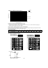
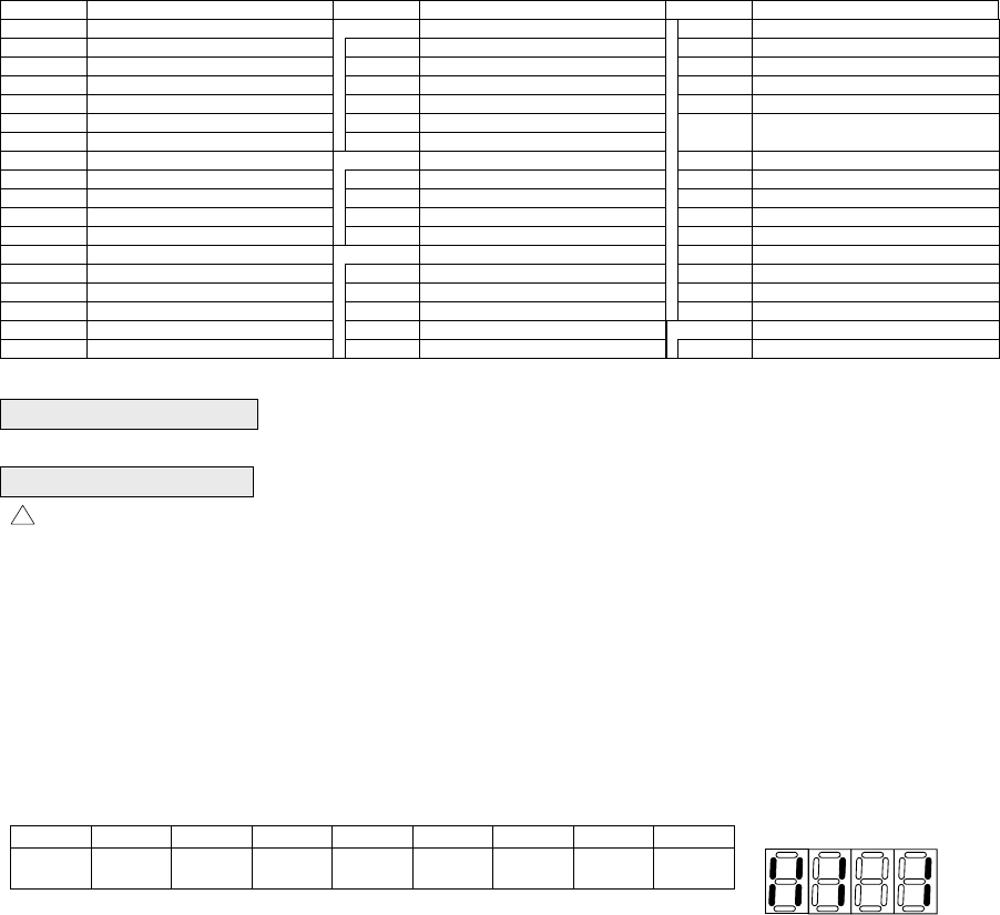
[Example]
When the compressor and
SV1 are turned during cooling
operation.
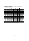
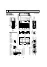
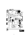
SYMBOL NAME SYMBOL NAME SYMBOL NAME
TB1 Terminal Block <Power Supply>
TB3 Terminal Block <Communication Line>
TB7 Terminal Block <
Centralized Control Line>
MC Motor For Compressor
MF1,MF2 Fan Motor
21S4 Solenoid Valve<Four-Way Valve>
SV1 Solenoid Valve<Bypass valve>
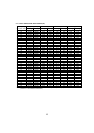
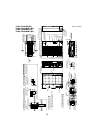
TH3
Thermistor<Outdoor Pipe>
TH4 Thermistor<Discharge/Compressor>
TH6 Thermistor<Low Pressure Saturated>
TH7
TH8
Thermistor<Outdoor>
Thermistor<Heatsink>
63HS High Pressure Sensor
63H High Pressure Switch
63L Low Pressure Switch
CE Main Smoothing Capacitor
ACTM
DCL
Active Filter Module
P.B. Power Circuit Board
Power Module
Connection Terminal<U/V/W-Phase>
TABU/V/W
C.B.
Fuse<T6,3AL250V>
F1,F2
Switch<Display Selection>
SW1
Switch<Function Selection>
SW2
Switch<Test Run>
SW3
Switch<Model Selection>
SW4
Switch<Function Selection>
SW5
Switch<Function Selection>
SW6
Switch<Function Selection>
SW7
Switch<Function Selection>
SW8
Switch<Unit Address Selection, 1st digit>
SWU1
Switch<Unit Address Selection, 2nd digit>
SWU2
LED<Operation Inspection Display>
LED1,LED2
LED<Power Supply to Main Microprocessor>
LED3
Controller Circuit Board
Connector<Connection For Option>
SS
Connector<Connection For Option>
CN3D
Connector<Connection For Option>
CN3S
Connector<Connection For Option>
CN3N
Connector<To N.F. Board CN52C>
(Symbol of Board is CNLVB)
CNLVB
Connector<Connection For Option>
CN51
Relay
X501~505
M-NET P.B.
ConnectionTerminal<Ground>
M-NET Power Circuit Board
TP1
Connection Terminal<L/N-Phase>
TABS/T
Connection Terminal<DC Voltage>
TABP1/P2/P
Connection Terminal<DC Voltage>
Diode Bridge
TABN1/N2/N
N.F. Noise Filter Circuit Board
Connection Terminal<L-Phase>
LI/LO
Connection Terminal<N-Phase>
NI/NO
Connection Terminal<Ground>
EI,E2
52C Relay
52C
IPM
DS2,DS3
Reactor
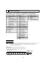
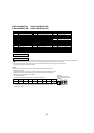
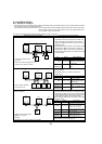
Bit
Indication
1
Compressor
operated
2
52C
3
21S4
4
SV1
5
(SV2)
6
-
7
-
8
Always lit
• During normal operation
• The LED indicates the drive state of the controller in the outdoor unit.
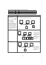
• When faults requiring inspection occurs
The LED alternately indicates the inspection code and the location of the unit in which
the fault has occurred.
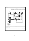
• Use copper supply wires.
NOTES:
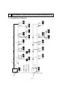
1.Refer to the wiring diagrams of the indoor units for details on wiring of each indoor unit.
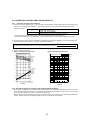
Self-diagnosis function
The indoor and outdoor units can be diagnosed automatically using the self-diagnosis switch
(SW1) and LED1, LED2 (LED indication) found on the multi-controller of the outdoor unit.
LED indication : Set all contacts of SW1 to OFF.
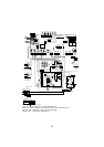
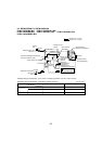
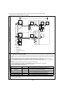
Cautions when Servicing
Caution for electrical work
!
•
WARNING: When the main supply is turned off, the voltage [340 V] in the main capacitor will drop to 20 V in approx. 2 minutes (input voltage: 230 V).
When servicing, make sure that LED1, LED2 on the outdoor circuit board goes out, and then wait for at least 1 minute.
• Components other than the outdoor board may be faulty: Check and take corrective action, referring to the service manual.
Do not replace the outdoor board without checking.
PUMY-P36NHMU(-BS) PUMY-P36NHMUR1(-BS)
PUMY-P48NHMU
2(-BS) PUMY-P48NHMUR3(-BS)