


26
8-3. SYSTEM CONTROL
8-3-1. Example for the System
• Example for wiring control cables, wiring method and address setting, permissible lengths, and the prohibited items are listed
in the standard system with detailed explanation.
The explanation for the system in this section : Use one single outdoor unit and multiple outdoor units for M-NET remote control system.
Use one single outdoor unit and multiple indoor units in the multiple outdoor units
for the M-NET remote control system.
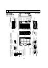
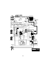
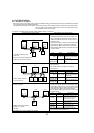
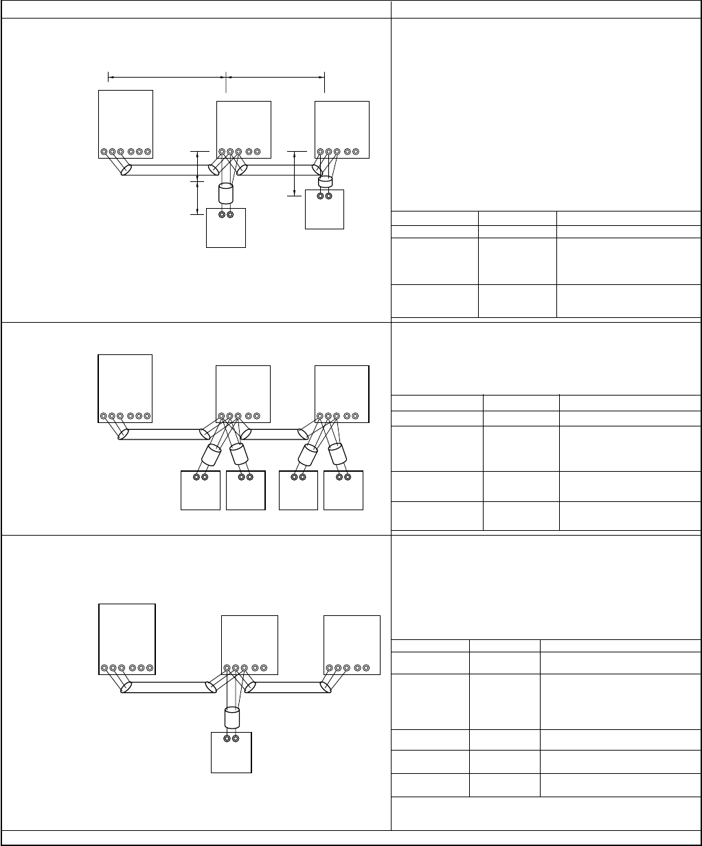
A. Example of a M-NET remote controller system (address setting is necessary.)
Example of wiring control cables
Wiring Method and Address Setting
• 1 remote controller for each
indoor unit.
• There is no need for setting the 100
position on the remote controller.
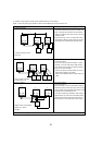
1. Standard operation
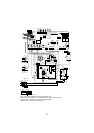
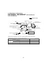
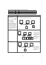
2. Operation using 2 remote controllers
•
Using 2 remote controllers
for each indoor unit.
M1M2
TB5
S12
TB15
01
101
IC
AB
M1M2
TB3
SAB
TB7
51
OC
L
1
L3
L2
S
M1M2
TB5
S12
TB15
02
IC
RC
102
AB
RC
l1
l2
M1M2
TB5
S12
TB15
01
101
RC
(Main)
151
IC
M1M2
TB3
SAB
TB7
51
OC
S
M1M2
TB5
S12
TB15
02
IC
RC
(Sub)
102
RC
(Main)
152
RC
(Sub)
AB AB AB AB
M1M2
TB5
S12
TB15
01
101
IC(Main)
AB
M1M2
TB3
SAB
TB7
51
OC
S
M1M2
TB5
S122
TB15
02
IC(Sub)
RC
a. Use feed wiring to connect terminals M1 and M2 on
transmission cable block (TB3) for the outdoor unit
(OC) to terminals M1 and M2 on the transmission
cable block (TB5) of each indoor unit (IC). Use non-
polarized 2 wire.
b. Connect terminals M1 and M2 on transmission cable
terminal block (TB5) for each indoor unit with the
terminal block (TB6) for the remote controller (RC).
c. Set the address setting switch (on outdoor unit P.C.B)
as shown below.
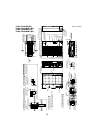
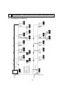
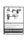
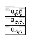
3. Group operation
• Multiple indoor units operated
together by 1 remote
controller
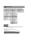
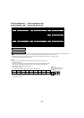
Unit
Indoor unit (IC)
Outdoor unit
(OC)
Remote
controller (RC)
Range
001 to 050
051 to 100
101 to 150
Setting Method
—
Use the smallest
address of all the indoor
unit plus 50.
Indoor unit address plus
100.
a. Same as above.
b. Same as above.
c. Set address switch (on outdoor unit P.C.B) as
shown below.
Unit
Indoor Unit (IC)
Outdoor unit
(OC)
Range
001 to 050
051 to 100
101 to 150
151 to 200
Setting Method
—
Use the smallest
address of all the indoor
units plus 50.
Indoor unit address plus
100.
Indoor unit address plus
150.
a. Same as above.
b. Connect terminals M1 and M2 on transmission cable
terminal block (TB5) of the IC main unit with the most
recent address within the same indoor unit (IC) group
to terminal block (TB6) on the remote controller.
c. Set the address setting switch (on outdoor unit P.C.B)
as shown below.
Unit
IC (Main)
IC (Sub)
Outdoor Unit
Main Remote
Controller
Sub Remote
Controller
Range
001 to 050
001 to 050
051 to 100
101 to 150
151 to 200
Setting Method
Use the smallest address within the
same group of indoor units.
Use an address, other than that of
the IC (Main) in the same group
of indoor units. This must be in
sequence with the IC (Main).
Use the smallest address of all the
indoor units plus 50.
Set at an IC (Main) address within
the same group plus 100.
Set at an IC (Main) address within
the same group plus 150.
d. Use the indoor unit (IC) within the group with the
most functions as the IC (Main) unit.
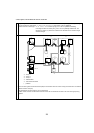
Main Remote
Controller (RC)
Sub Remote
Controller (RC)
Combinations of 1 through 3 above are possible.