


42
on
21345678
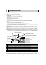
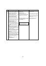
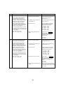
Overvoltage or voltage shortage
Abnormal if any of followings are detected
during compressor operation;
• Decrease of DC bus voltage to 310V
• Instantaneous decrease of DC bus voltage to
200V.
• Increase of DC bus voltage to 400V.
• Decrease of input current of outdoor unit to
0.5A only if operation frequency is more than
or equal to 40Hz or compressor current is
more than or equal to 5A.
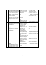
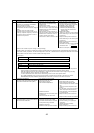
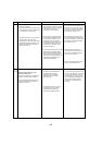
Temperature of heatsink
Abnormal if heat sink thermistor(TH8) detects
temperature indicated below 85 [185°F]
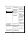
(1) Power module
Check abnormality by driving power module in
case overcurrent is detected.
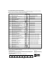
Display
Abnormal point and detecting method
Causes
Check points
4230
4250
4220
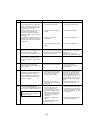
Decrease of power supply voltage
Disconnection of compressor wiring
Defective 52C
Defective ACT module
Disconnection or loose connection of
CN5 on the outdoor power circuit board
Defective 52C drive circuit of outdoor
power circuit board
Disconnection or loose connection of
CN2 on the outdoor power circuit board
Defective ACT module drive circuit of
outdoor controller circuit board
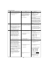
Disconnection or loose connection of CNAF
The outdoor fan motor is locked.
Failure of outdoor fan motor
Airflow path is clogged.
Rise of ambient temperature
Defective thermistor
Defective input circuit of outdoor power
circuit board
Failure of outdoor fan drive circuit
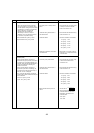
Outdoor stop valve is closed.
Decrease of power supply voltage
Looseness, disconnection or converse
of compressor wiring connection
Defective compressor
Defective outdoor power circuit board
Check the facility of power supply.
Correct the wiring (U·V·W phase) to
compressor. (Outdoor power circuit board).
P48NHMU
(1)
(-BS) : Replace 52C.
P36NHMU(-BS)/NHMUR1(-BS)
P48NHMU
2
(-BS)/MHMUR3(-BS) :
Replace noise filter circuit board
(Including 52C)
Replace ACT module.
(Refer to 9-9. Test point ; the item of ACTM)
Check CN5 wiring on the outdoor power
circuit board.
Replace outdoor power circuit board.
Check CN2 wiring on the outdoor power
circuit board.
Replace outdoor power circuit board.
Check CNAF wiring.
The 4220 error history can be confirmed
with SW1 No.189.
(Refer to 9-9. Test point ; the item of ACTM)
Check outdoor fan.
Check air flow path for cooling.
Check if there is something which
causes temperature rise around outdoor
unit.
(Upper limit of ambient temperature is 46
[115°F].)
Turn off power, and on again to check if
4230 is displayed within 30 minutes.
Check thermistor <TH8> temperature
by microprocessor.
Replace outdoor power circuit board.
Replace outdoor controller circuit board.
Open stop valve.
Check facility of power supply.
Correct the wiring (U·V·W phase) to
compressor.
(Outdoor power circuit board).
Check compressor.
Replace outdoor power circuit board.
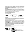
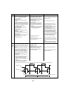
Notes in case of 4220 error (Over voltage or voltage shortage)
In PUMY models, bus voltage is controlled using ACTM. If ACTM is failed, bus voltage becomes uncontrollable and stops abnormally.
To check the normality of operation, see DC bus voltage SW1 9-10. No.45, or determine DC bus voltage of the both sides of condenser
C510 or CNDC connector which is on Multi controller board using a tester.
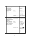
1. Check point
2. Check the voltage
Caution : Determine the voltage for 10 seconds after the compressor has operated. ACTM does not operate when the compressor is
stopping (Including constraint electric continuity) and for 10 seconds after the compressor start to operate.
When bus voltage is abnormal, see the table above (1.Check point) and check such as input voltage, wiring, 52C relay.
To check ACTM itsef, see 9-9. Test point ; the item of ACTM.
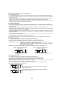
In case of ACTM failure, also check if there is the breaking of a wire in rush current protect resistor.
As for PUMY-P48NHMU
(1)
(-BS), rush current protect resistor is resistor RS (not mounted on the board). For PUMY-
P36NHMU/NHMUR1(-BS), P48NHMU
2
,/NHMUR3(-BS) resistor RS1 is mounted on noise filter circuit board.
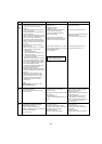
Self check switch No.45 SW1 : 10110100
Tester check
The voltage (DC) of the condenser C510 or CNDC connector which is on Multi controller board
ACTM condition DC bus voltage
Normal Target voltage 340-350V (DC)
Failure / no operation Less than 310V (DC) or over 400V (DC)
Contimued on the next page.