


73
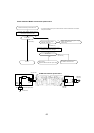
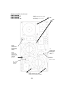
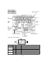
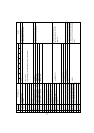
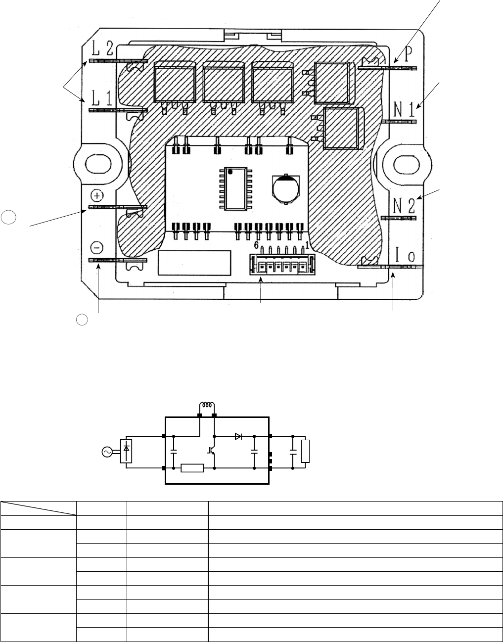
Active filter module
PUMY-P36NHMU(-BS)
PUMY-P36NHMUR1(-BS)
PUMY-P48NHMU
2(-BS)
PUMY-P48NHMUR3(-BS)
+
DCL
L1 L2
ACTM
P
Io
N1
N2
(+)
(- )
Load
Connection and internal circuit diagram
–
+
L1, L2
Connect to the
DCL (Reactor)
Connect to the
outdoor power
circuit board
(TABP1)
N2
Non-connect
N1
Non-connect
P
Connect to the outdoor power
circuit board (TABP2)
Connect to the outdoor power
circuit board (CNAF)
1 : GND
2-1 : 15V DC
3-1 : Control signal
4, 5 : Not used
6-1 : Control signal
Upper
side
Connect to the outdoor
power circuit board (TABN1)
Lower
side
lo
Connect to the outdoor power
circuit board (TABN2)
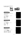
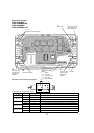
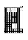
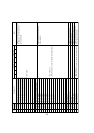
Error condition Normal value (reference)
Symptom when the unit is in trouble
(–) and Io open less than 1
"
1
The unit does not operate (can not be switched ON)
(–) and L2
short 100k
"
~ 1M
"
1
The breaker operates
open
W
1
The unit does not operate (can not be switched ON)
2
4220 Abnormal stop (9-10. No.189 "ACTM error" display)
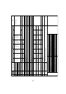
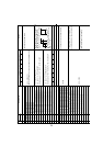
P and L2
short 100k
"
~ 1M
"
1
The breaker operates
open
W
1
The unit does not operate (can not be switched ON)
2
4220 Abnormal stop (9-10. No.189 "ACTM error" display)
P and Io
short 100k
"
~ 1M
"
1
The breaker operates
open
W
1
The unit does not operate (can not be switched ON)
2
4220 Abnormal stop (9-10. No.189 "ACTM error" display)
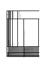
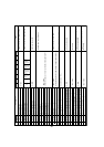
L2 and Io
short 100k
"
~ 1M
"
1
The breaker operates
open
W
1
The unit does not operate (can not be switched ON)
2
4220 Abnormal stop (9-10. No.189 "ACTM error" display)
Tester check points of Active fi lter module
W
The symptom when the unit is in open error condition is described to determine open error by tester check.