


89
OPERATING PROCEDURE
PHOTOS & ILLUSTRATION
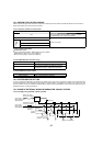
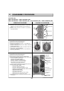
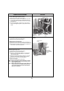
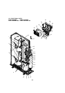
Photo 4
(6) Remove electrical parts box fixing screw (4 × 10) and
detach the electrical parts box by pulling it upward. The
electrical parts box is fixed with 2 hooks on the left and 1
hook on the right.
Electrical parts box
Electrical parts box fixing screw
From the previous page.
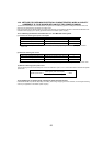
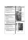
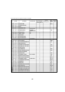
Photo 5
4.
Removing the thermistor <Low pressure saturated temp.>
(TH6)
(1) Remove the service panel. (See Figure 1)
(2) Remove the top panel. (See Figure 1)
(3) Disconnect the connector, TH6 and TH7 (red), on the Multi
controller board in the electrical parts box.
(4) Loosen the wire clamps on top of the electrical parts box.
(5) Pull out the thermistor <Low pressure saturated temp.>
(TH6) from the sensor holder.
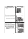
Note:
In case of replacing thermistor <Low pressure satu-
rated temp.> (TH6), replace it together with thermistor
<Outdoor> (TH7) since they are combined together.
Refer to No.5 below to remove thermistor <Outdoor>.
Thermistor
<TH6>
Electrical
parts box
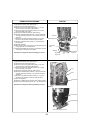
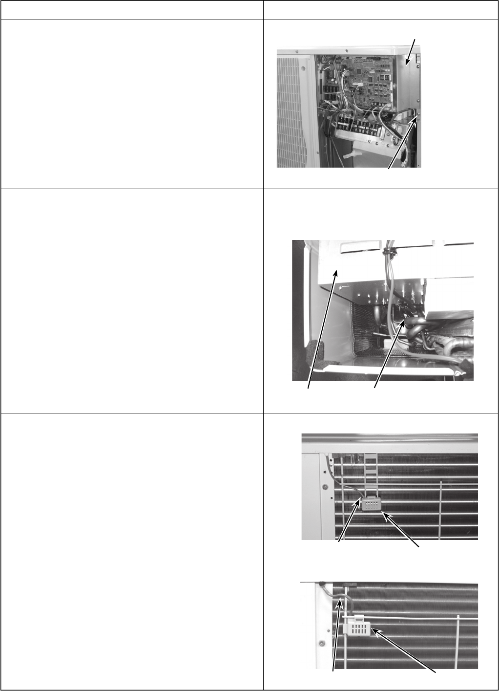
5. Removing the thermistor <Outdoor> (TH7)
(1) Remove the service panel. (See Figure 1)
(2) Remove the top panel. (See Figure 1)
(3) Disconnect the connector TH6 and TH7 (red) on the Multi
controller board in the electrical parts box.
(4) Loosen the wire clamps on top of the electrical parts box.
(See Photo 4)
(5) Pull out the thermistor <Outdoor> (TH7) from the sensor
holder.
Note: In case of replacing thermistor <Outdoor> (TH7),
replace it together with thermistor <Low pressure
saturated temp> (TH6), since they are combined
together.
Refer to No.4 above to remove thermistor <Low pres-
sure saturated temp>.
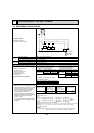
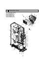
Photo 6
Lead wire of thermistor
<Outdoor> (TH7)
Sensor holder
Lead wire of thermistor <Outdoor> (TH7)
Sensor holder
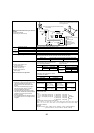
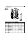
PUMY-P48NHMU(1)
PUMY-P36NHMU(R1)/P48NHMU(2),(R3)