


18
6
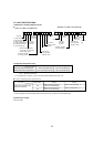
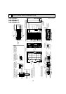
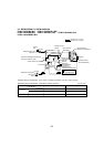
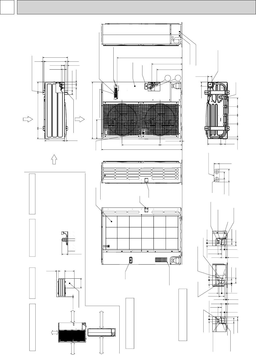
OUTLINES AND DIMENSIONS
PUMY-P48NHMU
PUMY-P48NHMU-BS
PUMY-P48NHMU
1
PUMY-P48NHMU1-BS
Unit : mm <inch>
Min.500mm
<19-11/16>
Min.500mm
<19-11/16>
Min.150mm
<5-29/32>
Min.10mm<3/8>
Handle
Side Air Intake
Front piping cover
Rear piping cover
Air intake
Rear Air Intake
Handle
Service panel
Handle
31<1-7/32>
74<2-19/32>
40<1-9/16>
Max.
30mm<1-3/16>
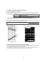
The diagram below shows a
basic example.
Explanation of particular details is
given in the installation manuals etc.
Dimensions of space needed
for service access are
shown in the below diagram.
<Foundation bolt height>
Please secure the unit firmly
with 4 foundation (M10<W3/8>)
bolts.(Bolts and washers must
be purchased locally.)
Air Discharge
Rear Air Intake
Side Air Intake
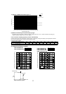
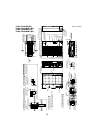
……Refrigerant GAS pipe connection (FLARE):15.88 (5/8 inch)
……Refrigerant LIQUID pipe connection (FLARE): 9.52 (3/8 inch)
+1…..Indication of STOP VALVE connection location.
Example of Notes
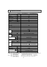
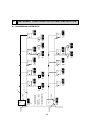
Piping Knockout Hole Details
1 FREE SPACE (Around the unit)
2 SERVICE SPACE 3 FOUNDATION BOLTS
4 PIPING-WIRING DIRECTIONS
Piping and wiring connections
can be made from 4 directions:
front, right, rear and below.
1/2 Conduit attachment
2-W22<7/8>
When installing the conduit.
Set the attachment to the
inner side of each panel.
mm<inch>
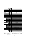
FOUNDATION
Service space
Min.1000mm<39-3/8>
Min.10mm<3/8>
Min.10mm<3/8>
FREE
Min.150mm<5-29/32>
Right trunking hole
(Knockout)
45<1-25/32>
40<1-9/16>
65<2-9/16>
92<3-5/8>
27<1-1/16>
55<2-3/16>
23<29/32>
73<2-7/8>
63<2-1/2>
Rear piping hole
(Knockout)
Rear trunking hole
(Knockout)
Conduit hole
(2-W27<1-1/16>Knockout)
W92
<3-5
/8>
W92
<3-5/8>
19<3/4>
55<2-3/16>
92<3-5/8>
40<1-9/16>
73<2-7/8>
63<2-1/2>
23<29/32>
27<1-1/16>
92<3-5/8>
Conduit hole
(2-W27<1-1/16>Knockout)
75
<2-31/32>
Right piping hole
(Knockout)
45<1-25/32>
40<1-9/16>
55<2-3/16>
73<2-7/8>
27<1-1/16>
23<29/32>
65<2-9/16>
92<3-5/8>
Conduit hole
(2-W27<1-1/16>Knockout)
Front trunking hole
(Knockout)
Front piping hole
(Knockout)
63
<2-1/2>
W92
<3-5/8>
30<1-3/16>
81<3-3/16>
219<8-5/8>
71<2-13/16>
71<2-13/16>
Bottom piping hole
(Knockout)
Drain hole
5-
W33<1-5/16>
220
<8-21/32>
145
<5-23/32>
145
<5-23/32>
145
<5-23/32>
Handle
600<23-5/8>
28<1-3/32> 370<14-9/16>
70<2-3/4>
56<2-7/32>
42<1-21/32>
56<2-7/32>
37<1-15/32>
19<3/4>
53<2-3/32>
417<16-13/32>
330<13>
175
<6-7/8>
175
<6-7/8>
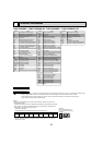
2-12%36 Oval hole
(Foundation Bolt M10<W3/8>)
2-U Shaped notched hole
(Foundation Bolt M10<W3/8>)
30<1-3/16>
1088<42-27/32>
322<12-11/16>
635<25>371<14-19/32>
950<37-13/32>
23<29/32>
1350<53-5/32>
+1 423<16-21/32>
+1 507<19-31/32>
Handle
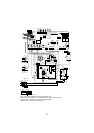
1
2
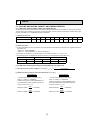
( )
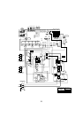
Left …… For the power supply
Center … For the transmission line
Right…… For concentration control
Terminal block
Ground for the transmission line
Ground for concentration control
Ground for the power supply
("GR"marking position)